
GCVM96 & GMVM96 Installation Instructions

28
WIRING HARNESS
The wiring harness is an integral part of this furnace. Wires
are color coded for identification purposes. Refer to the wiring
diagram for wire routings. If any of the original wire as supplied
with the furnace must be replaced, it must be replaced with
wiring material having a temperature rating of at least 105° C.
Any replacement wiring must be a copper conductor.
115 VOLT LINE CONNECTIONS
Before proceeding with electrical connections, ensure that the
supply voltage, frequency, and phase correspond to that speci-
fied on the unit rating plate. Power supply to the furnace must be
NEC Class 1, and must comply with all applicable codes. The
furnace must be electrically grounded in accordance with local
codes or, in their absence, with the latest edition of The National
Electric Code, ANSI NFPA 70 and/or The Canadian Electric Code
CSA C22.1.
Use a separate fused branch electrical circuit containing prop-
erly sized wire, and fuse or circuit breaker. The fuse or circuit
breaker must be sized in accordance with the maximum
overcurrent protection specified on the unit rating plate. An elec-
trical disconnect must be provided at the furnace location.
Connect hot, neutral, and ground wires as shown in the wiring
diagram located on the unit’s blower door. For direct vent appli-
cations, the cabinet opening to the junction box must be sealed
air tight using either an UL approved bushing such as Heyco
Liquid Tight or by applying non-reactive UL approved sealant to
bushing.
Line polarity must be observed when making field connections.
Line voltage connections can be made through either the right or
left side panel. The furnace is shipped configured for a right side
(left side for counterflows) electrical connection with the junction
box located inside the burner compartment. To make electrical
connections through the opposite side of the furnace, the junc-
tion box must be relocated to the other side of the burner com-
partment prior to making electrical connections. To relocate the
junction box, follow the steps shown below.
NOTE: Wire routing must not interfere with circulator blower
operation, filter removal, or routine maintenance.
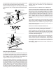
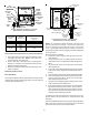
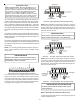
JUNCTION BOX RELOCATION
E
DGES
OF
SHEET
METAL
HOLES
MAY
BE
SHARP
.U
SE
GLOVES
AS
A
PRECAUTION
WHEN
REMOVING
HOLE
PLUGS
.
WARNING
T
O
PREVEN T
PERSONAL
INJU R Y
OR
DEATH
DUE
TO
ELECT RIC
SHOCK
,
DISCO NNECT
ELECT RICAL
POWER
BEFORE
INSTALLIN G
OR
SER V ICING
THIS
UNIT
.
WARNING
HIGHVOL TAGE!
T
O
AVOID
THE
RISK
OF
INJU R Y
,
ELECT R ICAL
SHOCK
OR
DEATH
,
THE
FURNACE
MUST
BE
ELECT R ICALLY
GROUND ED
IN
ACCORDANCE
WITH
LOCAL
CODES
OR
IN
THEIR
ABSENCE
,
WITH
THE
LATEST
EDIT ION
OF
THE
N
ATIONAL
E
LECT RIC
C
ODE
.US:NationalElectrical
Code(NEC)ANSI/N FPA70‐2011.InCANADA:
CanadianElectricalCodeCSAC22.1.
WARNING
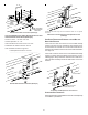
Line voltage connections can be made through either the right
or left side panel. The furnace is shipped configured for a right
side electrical connection. To make electrical connections
through the opposite side of the furnace, the junction box must
be relocated to the left side prior to making electrical connec-
tions. To relocate the junction box, perform the following steps.
1. Remove the burner compartment door.
2. Remove and save the two screws securing the junction
box to the side panel.
3. Relocate junction box and associated plugs and grommets
to opposite side panel. Secure with screws removed in
step 2.
WARNING
T
O
AVOID
THE
RISK
OF
INJU R Y
,
ELECT R ICAL
SHOCK
OR
DEAT H
,
THE
FURNACE
MUST
BE
ELECT R ICALLY
GROUND ED
IN
ACCORDANCE
WITH
LOCAL
CODES
OR
,
IN
THEIR
ABSENCE
,
WITH
THE
LATEST
EDITION
OF
THE
NATIONAL
E
LECTRICAL
C
ODE
.
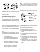
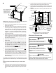
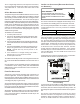
To ensure proper unit grounding, an earth ground wire must
be connected between the furnace ground screw located in-
side the furnace junction box and the electrical service panel.
NOTE: Do not use gas piping as an electrical ground. To con-
firm proper unit grounding, turn off the electrical power and per-
form the following check.
1. Measure resistance between the neutral (white) connection
and one of the burners.
2. Resistance should measure 10 ohms or less.
This furnace is equipped with a blower door interlock switch which
interrupts unit voltage when the blower door is opened for servicing.
Do not defeat this switch.
24 VOLT THERMOSTAT WIRING
W
IRE
RO UTING
MUST
NOT
INTERFERE
WITH
CIRCULATOR
BLOWER
OPERATION
,
FILTER
RE MOVAL
OR
RO UTINE
MAINTENANCE
.
A
RE MOVABLE
PLUG
CONNECTOR
IS
PROVIDED
WITH
THE
FUR N A CE
CO NTROL
TO
MAKE
THERMOSTAT
WIRE
CONNECTIONS
.T
HIS
PLUG
MAY
BE
RE MOVED
,
WIRE
CONNECTIONS
MADE
TO
THE
PLUG
,
AND
RE PLACED
.
I
T
IS
RECOMMENDED
THAT
MU LT IPLE
WIRES
BE
JOINE D
WITH
A
WIRE
NUT
AND
A
SINGLE
CO NDUCTOR
BE
INSER TED
UNDER
THE
TERMINA L
SCREW
.F
AILURE
TO
DO
SO
MAY
RESULT
IN
INTER MITTEN T
OPERATION
.
STRONGLY
IMPORTANT NOTE