
GCVM96 & GMVM96 Installation Instructions

25
RUBBER ELBOW
(EXTERNALLY
MOUNTED)
TUBE 1
GREEN HOSE
CLAMPS
(3 PLACES)
HOSE B
TUBE(S) 2
DRAIN TRAP
HOSE A
FRONT
COVER
DRAIN
PORT
RUBBER
ELBOW
DRAIN PORT
RED HOSE
CLAMP
SILVER HOSE CLAMP
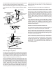
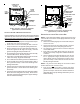
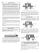
Upright “Alternate” Connections - Right Side
(Upflow Shown, Counterflow Similar)
ALTERNATE VENT/FLUE DRAIN HOSE CONNECTIONS
Upright installations using the alternate vent/flue outlet will require
“right-side only” drain hoses to be connected as follows.
Refer to
Vent/Flue Pipe and Combustion Air Pipe for details on alternate
vent/flue pipe connection.
1. Remove the rubber plug/cap from the right-side drain port
on the front cover . Save for use in step 3.
2. Secure Hose A to front cover drain port with a red hose
clamp. Route hose to rear right side panel grommet hole.
3. Remove grommet from front right-side panel drain hole.
Seal hole in grommet with large end of plug. Reinstall
grommet and plug into side panel drain hole.
4. Cut 1/4 inch from the end of the drain port on the externally
mounted rubber elbow. Discard cut portion.
5. Insert Tube 1 into rubber elbow drain port and secure with
a silver hose clamp. Angle tube toward trap.
6. Cut 17 3/4 inches from the long end of Hose B and discard.
7. Secure straight end of Hose B to exposed end of Tube 1
with a green hose clamp. Route hose toward right side
panel grommet holes.
8. Insert short end of one Tube 2 through rear right side panel
grommet drain hole. Secure tube to Hose A with a green
hose clamp.
9. Insert short end of remaining Tube 2 into Hose B from rubber
elbow and secure with green hose clamp. Ensure hoses
and tubes maintain a downward slope for proper drainage
and are not kinked or binding.
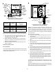
DRAIN
TRAP
FRONT
COVER
DRAIN PORT
TUBE(S) 2
GREEN
HOSE
CLAMPS
(3 PLACES)
RIGHT SIDE
PANEL
RUBBER ELBOW
DRAIN PORT
TUBE 1
SIDE PANEL
GROMMET
HOLES
HOSE
B
HOSE
A
RUBBER
ELBOW
RED HOSE
CLAMP
SILVER HOSE CLAMP
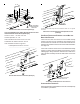
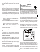
Upright “Standard” Connections - Right Side Only
(Upflow Shown, Counterflow Similar)
UPRIGHT INSTALLATIONS-TRAP ON LEFT SIDE
NOTE: For left side trap installation, grommets must be moved
to the left side of the furnace and the plugs installed on the right
side of the furnace.
1. Remove the rubber plug/cap from the left side drain port
on the front cover.
2. Secure Hose A to front cover drain port with a red hose
clamp. Route hose to rear side panel grommet hole.
3. Cut and remove 1/4 inch from the end of the drain port
on the rubber elbow.
4. Insert Tube 1 into rubber elbow drain port and secure
with silver hose clamp. Angle tube outward toward front
of furnace.
5. Refer to following Drain Hose B Table for hose “B” and
trim to appropriate length (determined by furnace
cabinet width). Secure remaining hose to Tube 1 with a
green hose clamp. Route other end of Hose B to front
left side panel grommet hole.
NOTE: Long hose “B” must always be connected to Tube 1
and the elbow and not on the front cover.
6. Insert short end of each Tube 2 through side panel
grommet holes. Secure tubes to Hose A and Hose B with
green hose clamps. Ensure hoses and tubes maintain a
downward slope for proper drainage and that they are not
kinked or binding.