
GCVM96 & GMVM96 Installation Instructions

24
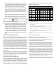
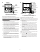
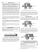
SIDE WALL VENT KIT
Vertical Installation
Horizontal Installation
Side Wall Vent Kit
This kit is to be used with 2” or 3” direct vent systems. The vent kit
must terminate outside the structure and may be installed with the
intake and exhaust pipes located side-by-side or with one pipe
above the other. This kit is NOT intended for use with single pipe
(indirect vent) installations.
Refer to the directions furnished with the Side Wall Vent Kit
(p/n 0170K00000S) for installation specifications.
C
ONDENSATE
D
RAIN
L
INES
& D
RAIN
T
RAP
A condensing gas furnace achieves its high level of efficiency by
extracting heat from the products of combustion to the point where
condensation takes place. The condensate must be collected in
the furnace drain trap and routed to an appropriate drain
location in compliance with local and national codes.
In upright installations, the furnace’s drain hoses may exit either
the right or left side of the furnace. NOTE: If the alternate vent/
flue outlet is utilized in an upright installation, the drain trap and
drain connections must be located on the same side as the alter-
nate vent/flue outlet.
In horizontal installations, the drain hoses will exit through the bot-
tom (down side) of the unit with the drain trap suspended beneath
the furnace. The field-supplied drain system must be in accor-
dance with all local codes and the instructions in the following
sections.
Follow the bullets listed below when installing the drain system.
Refer to the following sections for specific details concerning fur-
nace drain trap installation and drain hose hook ups.
• The drain trap supplied with the furnace must be used.
• The drain line between furnace and drain location must
meet local and nation codes.
• The drain line between furnace and drain location must
maintain a 1/4 inch per foot downward slope toward the
drain.
• Do not trap the drain line in any other location than at
the drain trap supplied with the furnace.
• If the drain line is routed through an area which may
see temperatures near or below freezing, precautions
must be taken to prevent condensate from freezing
within the drain line.
• If an air conditioning coil is installed with the furnace, a
common drain may be used. An open tee must be
installed in the drain line, near the cooling coil, to
relieve positive air pressure from the coil’s plenum.
This is necessary to prohibit any interference with the
function of the furnace’s drain trap.
NOTE: In vertical installations, air conditioning coil
condensate may drain into the furnace trap as long as there
is a trap between the coil and the furnace trap and the drain
pipe is not terminating below the water level of the furnace
trap.
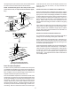
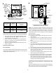
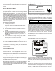
STANDARD RIGHT OR LEFT SIDE DRAIN HOSE CONNECTIONS
All installation positions require the use of the drain trap, hoses,
tubes, and clamps. The following quantity of hoses, tubes, and
hose clamps are provided with the unit.
DRAIN TRAP
QTY: 1
GREEN
HOSE CLAMPS
QTY: 3
SILVER
HOSE CLAMP
QTY: 1
TUBE 2
QTY: 2
TUBE 1
QTY: 1
HOSE B
QTY: 1
HOSE A
QTY: 1
RED
HOSE CLAMP
QTY: 1
Hose and Tube Identification
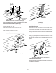
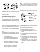
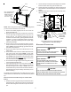
UPRIGHT INSTALLATIONS-TRAP ON RIGHT SIDE
In a upright installation drain hoses are connected to bottom drain
port on the rubber elbow and the recuperator coil front cover. The
drain lines are then routed through the right side panel and into the
drain trap secured to the outside of the cabinet.
NOTE: Refer to Alternate Vent/Flue Hose Connections for up-
right installations using an alternate vent/flue outlet.
1. Remove the rubber plug from the right side of the front cover
drain port.
2. Secure Hose A to front cover drain port with a red hose
clamp. Route hose to rear side panel grommet hole.
3. Cut and remove 1/4 inch from the end of the drain port on
the rubber elbow.
4. Insert Tube 1 into rubber elbow drain port and secure with
silver hose clamp. Angle tube outward toward front of furnace.
5. Cut 17 3/4 inches from the long end of Hose B and discard.
Secure the remaining hose to Tube 1 with a green hose
clamp. Route the other end of Hose B to front right side
panel grommet hole.
6. Insert short end of each of tube 2 through side panel
grommet holes. Secure tubes to hoses A and B with green
hose clamps. Ensure hoses and tubes maintain a downward
slope for proper drainage and that they are not kinked or
binding.