
GCVM96 & GMVM96 Installation Instructions

23
90º OR 45°
ELBOW
SCREEN
(OPTIONAL)
12" MIN. TO GRADE OR
HIGHEST ANTICIPATED
SNOW LEVEL
6” MAX
10”- 24”
4” MIN
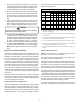
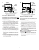
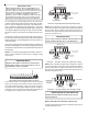
Standard Horizontal Terminations (Dual Pipe)
Vent & Combustion Air Intake Measurements for Stan-
dard Horizontal Terminations (Dual Pipe)
Center to center = 10” min / 24” max.
Vertical separation: 0” - 24”
Vent termination from wall = 8” min / 12” max.
Combustion air intake from wall = 6” max.
Vent and intake clearance to ground
or anticipated snow level = 12” min.
_____________________________________
SCREEN
(OPTIONAL)
AIR
INTAKE
90°
ELBOWS
12" MIN. ABOVE
HIGHEST ANTICIPATED
SNOW LEVEL
3” - 24”
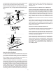
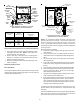
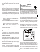
Alternate Horizontal Vent Termination (Dual Pipe)
SCREEN
(OPTIONAL)
AIR
INTAKE
90°
ELBOWS
12" MIN. ABOVE
HIGHEST ANTICIPATED
SNOW LEVEL
3”-24” BETWEEN PIPES
Combustion Air Intake may also be snorkeled to obtain 12” min ground
clearance.
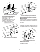
Alternate Vent Termination Above Anticipated Snow Level
(Dual Pipe)
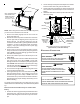
VENT/INTAKE TERMINATIONS FOR INSTALLATION OF MULTIPLE
DIRECT VENT FURNACES
If more than one direct vent furnace is to be installed vertically
through a common roof top, maintain the same minimum clear-
ances between the exhaust vent and air intake terminations of
adjacent units as with the exhaust vent and air intake terminations
of a single unit.
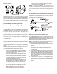
If more than one direct vent furnace is to be installed horizontally
through a common side wall, maintain the clearances as in the
following figure. Always terminate all exhaust vent outlets at the
same elevation and always terminate all air intakes at the same
elevation.
3” MIN
12” MIN TO GRADE OR HIGHEST
ANTICIPATED SNOW LEVEL
12” MIN SEPARATION
3” - 24”
OPTIONAL
INTAKE
SCREENS
Termination of Multiple Direct Vent Furnaces
CONCENTRIC VENT TERMINATION
Refer to the directions provided with the Concentric Vent Kit (DCVK)
for installation specifications.