
GCVM96 & GMVM96 Installation Instructions

22
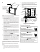
the last joist space to penetrate the header, two 45° elbows should
be used to reach the header rather than two 90° elbows.
NOTE: Terminate both pipes in the same pressure zone
(same side of roof, no major obstacles between pipes,
etc.).
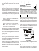
COMBUSTION AIR INTAKE
(OPTIONAL)
*Not required for
single pipe installation
TEE (OPTIONAL)
9
6
”
M
A
X
.
-
3
”
M
I
N
.
R
O
O
F
L
I
N
E
INTAKE
SCREEN
OPTIONAL
12” MIN
HEIGHT DIFFERENCE
BETWEEN
INTAKE AND VENT
12” MIN TO ROOF OR HIGHEST
ANTICIPATED SNOW LEVEL
STRAIGHT
ELBOWS
_____________________________________
VENT/FLUE TEE (
or
45° ELBOW
TURNED DOWN or
90° ELBOW TURNED
DOWN
OPTIONAL)
12" MIN. ABOVE
HIGHEST ANTICIPATED
SNOW LEVEL
12" MIN.
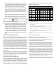
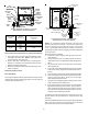
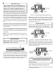
Horizontal Termination (Single Pipe)
Above Highest Anticipated Snow Level
DIRECT VENT (DUAL PIPE) PIPING
The inlet air screens provided in the installation instruction packet
are available for the installer to use in the inlet of the combustion air
pipe to prevent animals from building nests in the combustion air
pipe. Installation of screens, while strongly recommended, is not
required and will not affect performance of the unit.
Direct vent installations require both a combustion air intake and a
vent/flue pipe. The pipes may be run horizontally and exit through
the side of the building or run vertically and exit through the roof of
the building. The pipes may be run through an existing unused
chimney; however, they must extend a minimum of 12 inches
above the top of the chimney. The space between the pipes and
the chimney must be closed with a weather tight, corrosion resis-
tant flashing. Both the combustion air intake and a vent/flue pipe
terminations must be in the same atmospheric pressure zone.
Example: Same side of structure, no major obstacles be-
tween pipes, etc.
VENT/FLUE & COMBUSTION AIR PIPE LENGTHS &DIAMETERS
Refer to the following table for applicable length, elbows, and pipe
diameter for construction of the vent/flue and combustion air intake
pipe systems of a direct vent (dual pipe) installation. The number
of elbows tabulated represents the number of elbows and/or tees
in each (Vent/Flue & Combustion Air Intake) pipe. If there is a
difference between the two pipes, count the pipe with the most
fittings. Elbows and/or tees used in the terminations must be
included when determining the number of elbows in the piping
systems.
If the combustion air intake pipe is to be installed above a finished
ceiling or other area where dripping of condensate will be objec-
tionable, insulation of the combustion air pipe may be required.
Use 1/2” thick closed cell foam insulation such as Armaflex™ or
Insultube™ where required.
VENT/FLUE AND C OMBUSTION AIR PIPE TERMINATIONS
The vent/flue and combustion air pipes may terminate vertically, as
through a roof, or horizontally, as through an outside wall.
Refer to Vent/Flue Pipe and Combustion Pipe - Termination Loca-
tions for details concerning location restrictions. The penetrations
through the roof must be sealed tight with proper flashing such as
is used with a plastic plumbing vent.
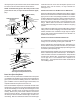
Horizontal terminations should be as shown in the following figure.
Refer to Vent/Flue Pipe and Combustion Pipe - Termination Lo-
cation for location restrictions. A 2 3/8” diameter wall penetration
is required for 2” diameter pipe. A 3” diameter hole is required for
a 2 1/2” pipe and a 3 1/2” diameter hole is required for 3”
diameter pipe. The wall penetration should be sealed with sili-
cone caulking material.