
GCVM96 & GMVM96 Installation Instructions

21
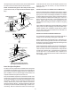
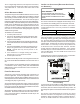
2. Remove the combustion air intake pipe from the furnace
and cut the pipe at the basepan coupling. Save the basepan
coupling and gasket from the blower deck coupling for use
in the alternate location. Discard the remaining pipe.
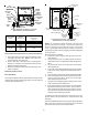
3. Remove plastic plug from alternate combustion air intake
location. Relocate and install plug in standard air intake
location (basepan). Grommet the remaining hole in the
blower deck with the plastic plug included in the drain kit
bag.
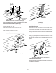
4. With the gasket facing the cabinet side panel, and the
flange’s flat spot facing forward, secure the combustion air
intake coupling to the cabinet using the screws removed in
step 1 or with field-supplied 3/8” #8 self -tapping screws.
B
E
SURE
NOT
TO
DAM AGE
INTERN A L
WIRING
OR
OTHER
CO MPONE NTS
WHEN
REINSTALLING
COUPLING
AND
SCREWS
.
CAUTION
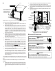
5. For non-direct vent installations installed horizontally, a
minimum of one 90° elbow should be installed on the
combustion air intake coupling to guard against inadvertent
blockage. No elbow is required on the alternate combustion
air intake of upright installations, however, a minimum
clearance of 2 inches is required to assure proper air supply.
6. For direct vent installations, secure field-supplied
combustion air intake pipe directly to the air intake coupling.
NOTE: A PVC coupling or elbow is required on counterflow
units.
NON-DIRECT VENT (SINGLE PIPE) PIPING
Non-direct vent installations require only a vent/flue pipe. The vent
pipe can be run horizontally with an exit through the side of the
building or run vertically with an exit through the roof of the building.
The vent can also be run through an existing unused chimney;
however, it must extend a minimum of 12 inches above the top of
the chimney. The space between the vent pipe and the chimney
must be closed with a weather-tight, corrosion-resistant flashing.
For details concerning connection of the vent/flue pipe to the fur-
nace, refer to Vent/Flue Pipe and Combustion Air - Standard Fur-
nace Connections or Alternate Furnace Connections for specific
details. Refer to the following Non-Direct Vent (Single Pipe) Piping
- Vent/Flue Pipe Terminations for specific details on termination
construction.
Although non-direct vent installations do not require a combustion
air intake pipe, a minimum of one 90° elbow should be attached to
the furnace’s combustion air intake. This elbow will guard against
inadvertent blockage of the air intake.
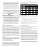
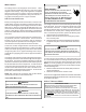
VENT/FLUE P IPE L ENGTHS AND DIAMETERS
Refer to the following table for applicable length, elbows, and pipe
diameter for construction of the vent/flue pipe system of a non-
direct vent installation. In addition to the vent/flue pipe, a single 90°
elbow should be secured to the combustion air intake to prevent
inadvertent blockage. The tee used in the vent/flue termination
must be counted as an elbow when determining the number of
elbows in the piping system.
012345678
60,000
2
or 2 1/2
250 245 240 235 230 225 220 215 210
80,000
2
or 2 1/2
250 245 240 235 230 225 220 215 210
80,000 3 250 243 236 229 222 215 208 201 194
100,000
2
or 2 1/2
90 85 80 75 70 65 60 55 50
100,000 3 250 243 236 229 222 215 208 201 194
115,000
2
or 2 1/2
75 70 65 60 55 50 45 40 35
115,000 3 220 213 206 199 192 185 178 171 164
*MVM9/*CVM9 Direct Vent (2 - Pipe) and Non-Direct Vent (1- Pipe)
(6)
Maximum Allowable Length of Vent/Flue Pipe & Combustion Air Pipe (ft)
(1) (2)
Unit Input
(Btu)
Pipe Size
(4)
(in.)
Number of Elbows
(3) (5)
1) Maximum allowable limits listed on individual lengths for inlet and flue
and NOT a combination.
2) Minimum requirement for each vent pipe is five (5) feet in length and
one elbow/tee.
3) Tee used in the vent/flue termination must be included when determin-
ing the number of elbows in the piping system.
4) 2 1/2” or 3” diameter pipe can be used in place of 2” diameter pipe.
5) Increased Clearance Configurations using (2) 45 deg.
elbows should
be considered equivalent to one 90 deg. elbow.
6) One 90° elbow should be secured to the combustion air intake con-
nection.
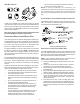
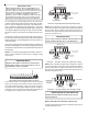
VENT/FLUE P IPE T ERMINATIONS
NOTE: If either a 90 degree or 45 degree elbow is used for
termination, it must be pointed downward.
The vent/flue pipe may terminate vertically, as through a roof, or
horizontally, as through an outside wall.
Vertical vent/flue pipe terminations should be as shown in the fol-
lowing figure. Refer to Vent/Flue Pipe and Combustion Air Pipe -
Termination Locations for details concerning location restrictions.
The penetration of the vent through the roof must be sealed tight
with proper flashing such as is used with a plastic plumbing vent.
Horizontal vent/flue pipe terminations should be as shown in the
following figure. Refer to Vent/Flue Pipe and Combustion Air Pipe
- Termination Locations for details concerning location restrictions.
A 2 3/8” diameter wall penetration is required for 2” diameter pipe.
A 3” diameter hole is required for a 2 1/2” pipe and a 3 1/2” diam-
eter hole is required for 3” diameter pipe. The wall penetration
should be sealed with silicone caulking material.
In a basement installation, the vent/flue pipe can be run between
joist spaces. If the vent pipe must go below a joist and then up into