
GCVM96 & GMVM96 Installation Instructions

19
SPECIAL VENTING REQUIREMENTS FOR INSTALLATIONS IN
CANADA
All installations in Canada must conform to the requirements
of CAN/CSA B149.1 code. All vent system components, in-
cluding primer and cement, must be listed to ULC S636. The
certified pipe and fittings should be clearly marked with the
ULC standard “S636”. The primer and cement used must be
of the same manufacturer as the vent system. For Royal Pipe
System 636; use GVS-65 Primer (Purple) and GVS-65 PVC
Solvent Cement. For IPEX System 636, use PVC/CPVC
Primer, Purple or clear. Use PVC Solvent Cement (Gray).
For Canadian installations, ABS may be used as a combus-
tion air pipe only. ABS is not an approved vent material in
Canada. If ABS is used as a combustion air pipe, it must be
CSA certified. Always follow the manufacturer’s instructions
in the use of primer and cement. Do not use primer and ce-
ment around potential sources of ignition. Do not use primer
or cement beyond its expiration date.
The safe operation, as defined by ULC S636, of the vent sys-
tem is based on following these installation instructions, the
vent system manufacturer’s installation instructions, and proper
use of primer and cement. It is recommended under this stan-
dard, that the vent system be checked once a year by quali-
fied service personnel. All fire stops and roof flashings used
with this system must be UL listed. Acceptability under CAN/
CSA B149.1 is dependent upon full compliance with all instal-
lation instructions. Consult the authority having jurisdiction
(gas inspection authority, municipal building department, fire
department, etc.) before installation to determine the need to
obtain a permit. *IPEX System 636™ is a trademark of IPEX
Inc.
Carefully follow the pipe manufacturers’ instructions for cutting,
cleaning, and solvent cementing PVC and/or ABS.
The vent can be run through an existing unused chimney provided
the space between the vent pipe and the chimney is insulated and
closed with a weather-tight, corrosion-resistant flashing.
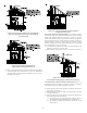
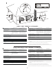
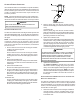
STANDARD FURNACE CONNECTIONS
It is the responsibility of the installer to ensure that the piping
connections to the furnace are secure, airtight, and adequately
supported.
Upflow/horizontal models are shipped with one 2" rubber cou-
pling to attach the vent pipe to the furnace. Counterflow/hori-
zontal models are shipped with two 2" rubber couplings for
attaching the vent pipe and combustion air pipe/fitting to the
furnace. Rubber couplings are typically shipped in the furnace
drain trap.
VENT/FLUE P IPE
Vent/flue pipe can be secured to the vent/flue coupling using the
rubber coupling and worm gear hose clamps provided with this
furnace (see “Standard Connections” figure). The rubber coupling
allows separation of the vent/flue pipe from the furnace during ser-
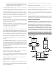
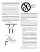
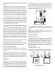
vicing. Combustion Air and Vent piping should be routed in a man-
ner to avoid contact with refrigerant lines, metering devices, con-
densate drain lines, etc. If necessary, clearances may be
increased by creating an offset using two 45 degree elbows.
This joint can be rotated on the fitting to establish maximum clear-
ance between refrigerant lines, metering devices, and conden-
sate drain lines, etc. This joint is the equivalent of one 90 deg.
elbow when considering elbow count.
45 DEGREE
ELBOWS
Increased Clearance Configuration
The vent/flue pipe can also be secured using a PVC or ABS elbow
or coupling using the appropriate glue (see Materials and Joining
Methods).
NOTE: For non-direct vent installations, a minimum of one 90°
elbow should be installed on the combustion air intake coupling to
guard against inadvertent blockage.
COMBUSTION A IR P IPE
DIRECT VENT INSTALLATIONS
On upflow units secure the combustion air intake pipe directly to
the air intake coupling. On counterflow units secure the combus-
tion air intake pipe to the air intake coupling using the rubber cou-
pling and worm gear hose clamps provided with the unit. The coun-
terflow rubber coupling allows service removal of air intake piping
internal to the furnace blower compartment. The combustion air
intake pipe can also be secured directly to the counterflow unit air
intake pipe coupling.
NON-DIRECT VENT INSTALLATIONS
A minimum of one 90° elbow should be installed on the combus-
tion air intake “coupling” to guard against inadvertent blockage.
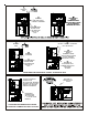
RUBBER
COUPLING
WITH WORM
GEAR CLAMPS
RUBBER
COUPLINGS
WITH WORM
GEAR CLAMPS
COMBUSTION
AIR PIPE
(DIRECT VENT ONLY)
COMBUSTION
AIR PIPE
(DIRECT VENT ONLY)
VENT/FLUE
PIPE
VENT/FLUE
PIPE
90 PVC
ELBOW
(NON-DIRECT VENT)
90 PVC
ELBOW
(NON-DIRECT VENT)
Standard Connections
OR
OR
UPFLOW COUNTERFLOW