
GCVM96 & GMVM96 Installation Instructions

14
Recommended Installation Positions
H
ORIZONTAL
A
PPLICATIONS
& C
ONSIDERATIONS
When installing a furnace horizontally, additional consideration must
be given to the following:
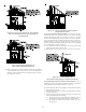
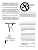
FURNACE SUSPENSION
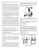
If suspending the furnace from rafters or joists, use 3/8" threaded
rod and 2”x2”x1/8” angle iron as shown in the following diagram.
The length of rod will depend on the application and the clearances
necessary.
If the furnace is installed in a crawl space it must be suspended
from the floor joist or supported by a concrete pad. Never install
the furnace on the ground or allow it to be exposed to water.
2" 2" 3/8"
ANGLE
IRON
(3
PLACES
)
XX
DRAIN T RAP AND LINES
In horizontal applications the condensate drain trap is secured to
the furnace side panel, suspending it below the furnace. A mini-
mum clearance of 4 3/4 inches below the furnace must be pro-
vided for the drain trap. Additionally, the appropriate downward
piping slope must be maintained from the drain trap to the drain
location. Refer to Condensate Drain Trap and Lines for further de-
tails. If the drain trap and drain line will be exposed to temperatures
near or below freezing, adequate measures must be taken to pre-
vent condensate from freezing.
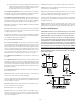
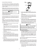
LEVELING
Leveling ensures proper condensate drainage from the heat ex-
changer and induced draft blower. For proper flue pipe drainage,
the furnace must be level lengthwise from end to end. The furnace
should also be level from back to front or have a slight tilt with the
access doors downhill (approximately 3/4 inches) from the back
panel. The slight tilt allows the heat exchanger condensate, gen-
erated in the recuperator coil, to flow forward to the recuperator coil
front cover.
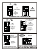
ALTERNATE E LECTRICAL AND GAS LINE CONNECTIONS
This furnace has provisions allowing for electrical and gas line con-
nections through either side panel. In horizontal applications the
connections can be made either through the “top” or “bottom” of
the furnace.
DRAIN PAN
A drain pan must be provided if the furnace is installed above a
conditioned area. The drain pan must cover the entire area under
the furnace (and air conditioning coil if applicable).
FREEZE PROTECTION
Refer to Horizontal Applications and Conditions - Drain Trap and
Lines.
P
ROPANE
G
AS
/H
IGH
A
LTITUDE
I
NSTALLATIONS
WARNING
P
OSSIBLE
PROPERTY
DAMAGE
,
PERSONAL
INJU R Y
OR
DEAT H
MAY
OCCUR
IF
THE
CORRECT
CONVERSION
KITS
ARE
NOT
INSTALLED
.T
HE
APPRO PRIATE
KITS
MUST
BE
APPLIED
TO
ENS U RE
SAFE
AND
PROPER
FURNACE
OPERATION
.A
LL
CONVERSIONS
MUST
BE
PERFORMED
BY
A
QU A LIFIED
INSTALLER
OR
SERVICE
AGENCY
.
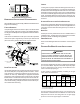
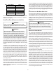
This furnace is shipped from the factory configured for natural gas
up to 10,000 ft. altitude. Propane conversions require the proper
LP kit to compensate for the energy content difference be-
tween natural and propane gas.
LP kits include a manifold assembly, including an LP gas
valve, orifices and LP burners.
High
Stage
Low Stage
(50% firing
rate)
Natural None
#45
1
3.5" w.c. 1" w.c. None
Propane LPKMOD*****
1.25MM
2
10.0" w.c. 2.6" w.c. None
NOTE:
In Canada, gas furnaces are only certified to 4500 feet.
Orifice
2
Except 115,000 BTU: #55
1
Except 115,000 BTU: #43
Gas
0-10,000
Manifold Pressure
Pressure
Switch
Change
Altitude Kit
For furnaces being converted to LP gas, it is strongly recom-
mended that a LPLP03 kit also be installed. The use of this kit
will prevent the furnace from firing when the LP gas supply
pressure is too low to support proper combustion.