
Installation Instructions Comfort Bridge Models

41
CAUTION
to PreVent unrelIaBle oPeratIon or equIPMent
DaMage, tHe Inlet gas suPPlY Pressure Must
Be as sPecIfIeD on tHe unIt ratIng Plate wItH
all otHer HouseHolD gas fIreD aPPlIances
oPeratIng.
The line pressure supplied to the gas valve must be within
the range specied below. The supply pressure can be
measured at the gas valve inlet pressure tap or at a hose
tting installed in the gas piping drip leg. The supply
pressure must be measured with the burners operating.
To measure the gas supply pressure, use the following
procedure.
1. Turn OFF gas to furnace at the manual gas shutoff
valve external to the furnace.
2. Connect a calibrated water manometer (or appropriate
gas pressure gauge) at either the gas valve inlet
pressure tap or the gas piping drip leg. See White-
Rodgers 36J54 gas valve (Figure 43B) fto locate the
inlet pressure tap.
note: If usIng tHe Inlet Pressure taP on tHe wHIte-
roDgers 36j54 gas ValVe, tHen use tHe 36g/j ValVe
Pressure cHeck kIt, Part no. 0151k00000s.
3. Turn ON the gas supply and operate the furnace and
all other gas consuming appliances on the same gas
supply line.
4. Measure furnace gas supply pressure with burners
ring. Supply pressure must be within the range
specied in the Inlet Gas Supply Pressure table.
If supply pressure differs from table, make the necessary
adjustments to pressure regulator, gas piping size, etc.,
and/or consult with local gas utility.
5. Turn OFF gas to furnace at the manual shutoff valve
and disconnect manometer. Reinstall plug before
turning on gas to furnace.
6. Turn OFF any unnecessary gas appliances stated in
step three.
gas ManIfolD Pressure MeasureMent anD
aDjustMent
CAUTION
to PreVent unrelIaBle oPeratIon or equIPMent
DaMage, tHe gas ManIfolD Pressure Must Be as
sPecIfIeD on tHe unIt ratIng Plate. onlY MInor
aDjustMents sHoulD Be MaDe BY aDjustIng tHe
gas ValVe Pressure regulator.
8. Replace the burner compartment door.
9. Open the manual gas shutoff valve external to the
furnace.
10. Turn on the electrical power to the furnace.
11. Adjust the thermostat to a setting above room
temperature.
12. After the burners are lit, set the thermostat to desired
temperature.
furnace sHutDown
1. Set the thermostat to the lowest setting.
The integrated control will close the gas valve and
extinguish ame. Following a 15 second delay, the
induced draft blower will be de-energized. After
the blower off delay time expires, the blower de-
energizes.
2. Remove the burner compartment door and move the
furnace gas valve manual control to the OFF position.
3. Close the manual gas shutoff valve external to the
furnace.
4. Replace the burner compartment door.
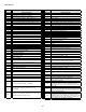
gas suPPlY Pressure MeasureMent
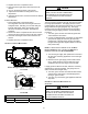
White-Rodgers Model 36J54 (Two-Stage)
fIgure 62a
Inlet
Pressure
Boss
Low Fire
Regulator
Adjust
M
a
n
o
m
e
t
e
r
M
a
n
o
m
e
t
e
r
H
o
s
e
High Fire Regulator
Adjust
Regulator
Vent
Outlet
Pressure Boss
Open to
Atmosphere
O
n
/
O
f
f
S
w
i
t
c
h
H
i
g
h
F
i
r
e
C
o
i
l
T
e
r
m
i
n
a
l
(
H
I
)
C
o
a
x
i
a
l
C
o
i
l
T
e
r
m
i
n
a
l
(
M
)
Common
Terminal(C)
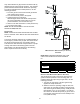
White-Rodgers Model 36J54 Connected to Manometer
fIgure 62B
Natural Gas Minimum: 4.5" w.c. Maximum: 10.0" w.c.
Propane Gas Minimum: 11.0" w.c. Maximum: 13.0" w.c.
INLET GAS SUPPLY PRESSURE