
Installation Instructions Comfort Bridge Models

39
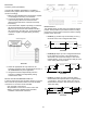
raMPIng ProfIles
The variable-speed circulator offers four different ramping
proles. These proles may be used to enhance cooling
performance and increaqse comfort level. Select ramping
proles on the user menu.
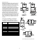
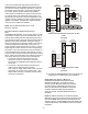
• Prole A (1) provides only an OFF delay of one (1)
minute at 100% of the cooling demand airow.
OFF
100% CFM 100% CFM
1 min
OFF
fIgure 58
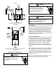
• Prole B (2) ramps up to full cooling demand airow
by rst stepping up to 50% of the full demand for
30 seconds. The motor then ramps to 100% of the
required airow. A one (1) minute OFF delay at 100%
of the cooling airow is provided.
50% CFM
1/2 min
100% CFM
100% CFM
1 min
OFF
OFF
fIgure 59
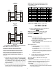
• Prole C (3) ramps up to 85% of the full cooling
demand airow and operates there for approximately
7 1/2 minutes. The motor then steps up to the full
demand airow. Prole C also has a one (1) minute
100% OFF delay.
100% CFM
OFF
OFF
fIgure 60
a
ccessorIes
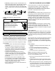
Accessory Control (Ventilators)
If an external humidier, dehumidier or ventilator is
installed, it may require airow from the HVAC system to
function accordingly.
1. Make sure the installed 24VAC thermostat is capable
of controlling the accessory or accessories.
2. Connect the appropriate accessory control wires
to the accessory devices from the thermostat
(see thermostat manual for connection and setup
instructions).
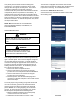
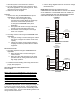
3. If the thermostat is capable of providing a continuous
fan call (G signal) during accessory operation:
Make sure to connect the thermostat G terminal to
the G terminal on the indoor unit. Setup thermostat
to ensure G signal is energized during accessory
operation.
fIgure 57
4. Select the appropriate fan only airow for the
accessory using the indoor unit push button menus or
the CoolCloud HVAC phone application.
5. Using the thermostat, independently test each
accessory in addition to independently testing
continuous fan mode.
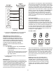
oPtIonal low Voltage HuMIDIfIer connectIon
Furnaces produced mid 2019 and later will have a 4” brown
wire on the low re pressure switch for 24 volt humidier
connection. To connect a 24 volt humidier:
• Turn off power to the furnace
• Strip insulation from the end of the 4” brown wire.
• Refer to connection diagram below and follow
humidier manufacturer instructions.