
Installation Instructions Comfort Bridge Models

27
The gas piping supplying the furnace must be properly
sized based on the gas ow required, specic gravity of the
gas, and length of the run. The gas line installation must
comply with local codes, or in their absence, with the latest
edition of the National Fuel Gas Code, NFPA 54/ANSI
Z223.1 or CAN/CSA B149.1-15.
To connect the furnace to the building’s gas piping, the
installer must supply a ground joint union, drip leg, manual
shutoff valve, and line and ttings to connect to gas valve.
In some cases, the installer may also need to supply a
transition piece from 1/2” pipe to a larger pipe size.
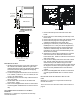
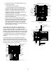
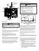
The following stipulations apply when connecting gas
piping. Refer to Gas Piping Connections gure for typical
gas line connections to the furnace.
• Gas piping must be supported external to the furnace
cabinet so that the weight of the gas line does not
distort the burner rack, manifold or gas valve.
• Use black iron or steel pipe and ttings for building
piping. Where possible, use new pipe that is properly
chamfered, reamed, and free of burrs and chips. If
old pipe is used, be sure it is clean and free of rust,
scale, burrs, chips, and old pipe joint compound.
• Use pipe joint compound on male threads ONLY.
Always use pipe joint compound (pipe dope) that is
APPROVED FOR ALL GASSES. DO NOT apply
compound to the rst two threads.
• Use ground joint unions.
• Install a drip leg to trap dirt and moisture before it can
enter the gas valve. The drip leg must be a minimum
of three inches long.
• Install a 1/8” NPT pipe plug tting, accessible for test
gage connection, immediately upstream of the gas
supply connection to the furnace.
• Always use a back-up wrench when making the
connection to the gas valve to keep it from turning.
The orientation of the gas valve on the manifold must
be maintained as shipped from the factory. Maximum
torque for the gas valve connection is 375 in-lbs;
excessive over-tightening may damage the gas valve.
• Install a manual shutoff valve between the gas
meter and unit within six feet of the unit. If a union
is installed, the union must be downstream of the
manual shutoff valve, between the shutoff valve and
the furnace.
• Tighten all joints securely.
• Connection method must be in compliance with all
local and national codes. US: National Fuel Gas
Code (NFGC) NFPA 54-2015/ANSI Z223.1-2015 and
the Installation Standards, Warm Air Heating and Air
Conditioning Systems ANSI/NFPA 90B
In Canada, CANADA: National Standard of
Canada, Natural Gas and Propane Installtion Code
(NSCNGPIC) CAN/CSA B149.1-15
This unit is congured for natural gas. The appropriate
manufacturer’s propane gas conversion kit, must be
applied for propane gas installations. Refer to the Propane
Gas and/or High Altitude Installations for details.
Consult the furnace Specication Sheet for a listing of
appropriate kits. The indicated kits must be used to insure
safe and proper furnace operation. All conversions must
be performed by a qualied installer, or service agency.
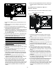
gas ValVe
This unit is equipped with a 24 volt gas valve controlled
during furnace operation by the integrated control
module. As shipped, the valve is congured for natural
gas. The valve is eld convertible for use with propane
gas by replacing the regulator spring with a propane
gas spring from an appropriate manufacturer’s propane
gas conversion kit. Taps for measuring the gas supply
pressure and manifold pressure are provided on the valve.
The gas valve has a manual ON/OFF control located on
the valve itself. This control may be set only to the “ON”
or “OFF” position. Refer to the lighting instructions label
or Startup Procedure & Adjustment for use of this control
during start up and shut down periods.
WARNING
to aVoID PossIBle unsatIsfactorY oPeratIon
of equIPMent DaMage Due to unDerfIrIng or
equIPMent, use tHe ProPer sIZe of natural/
ProPane gas PIPIng neeDeD wHen runnIng PIPe
froM tHe Meter/tank to tHe furnace.
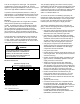
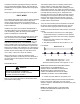
gas PIPIng connectIons
½
”
¾
”
1
”
1¼” 1 ½”
10 132
278 520 1050 1600
20 92 190 350 730 1100
30 73 152 285 590 980
40 63 130 245 500 760
50 56 115 215 440 670
60 50 105 195 400 610
70 46 96 180 370 560
80 43 90 170 350 530
90 40 84 160 320 490
100 38 79 150 305 460
CFH = BTUH Furnace Input _______________
_________
Heating Value of Gas (BTU/Cubic Foot)
Natural Gas Capacity of Pipe
In Cubic Feet of Gas Per Hour (CFH)
Nominal Black Pipe Size
Length of
Pipe in Feet
(Pressure 0.5 psig or less and pressure drop of 0.3" W.C.; Based on
0.60 Specific gravity Gas)