
Installation Instructions Comfort Bridge Models

16
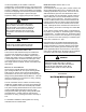
non-DIrect Vent InstallatIons
A minimum of one 90° elbow should be installed on
the combustion air intake “coupling” to guard against
inadvertent blockage.
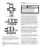
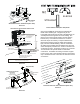
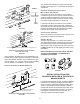
alternate Vent/flue locatIon
The alternate vent/ue location is the large hole directly
in line with the induced draft blower outlet. To use the
alternate vent/ue location refer to the following steps and
the “Alternate Vent/Flue Location” gure. This option is not
available with counter-ow models.
note: In tHe HorIZontal left InstallatIon
PosItIon, a Means of conDensate collectIon Must
Be ProVIDeD to keeP Vent PIPe conDensate froM
enterIng tHe Draft InDucer HousIng. If tHe Vent
DraIn elBow Is elIMInateD froM tHe InstallatIon, an
rf000142 kIt Must Be useD.
1. Remove the four screws from the vent pipe ange on
top the furnace.
2. Remove the internal elbow and vent pipe.
3. Cut 2 1/2” from the ange.
4. Remove plastic plug in line with the inducer outlet
5. Install cut end of the anged section and connect to
inducer with rubber coupling supplied with furnace.
6. Install screws removed in step 1, securing the ange
to the cabinet.
CAUTION
Be sure not to DaMage Internal wIrIng or otHer
coMPonents wHen reInstallIng couPlIng anD
screws.
fIgure 11
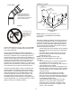
WARNING
tHe ruBBer elBow Is not DesIgneD to suPPort
a loaD. wHen tHe ruBBer elBow Is MounteD
externallY to tHe furnace caBInet, extreMe
care Must Be taken to aDequatelY suPPort fIelD-
suPPlIeD Vent/flue PIPIng, as DaMage can result
In leaks causIng BoDIlY InjurY or DeatH Due
to exPosure to flue gases, IncluDIng carBon
MonoxIDe.
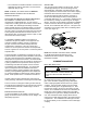
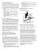
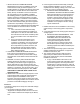
COMBUSTION AIR INTAKE OPTIONS: The RF000142
coupling can be secured directly to the furnace intake
coupling if condensation is a concern. If the RF000142 is
used on the combustion air inlet, it must be installed with
the arrow pointing up. It should be noted, the combustion
air will actually be moving in a direction opposite of the
arrow on the RF000142 coupling. It must have a eld
supplied, trapped drain tube free-draining to proper
condensate disposal location. A loop in the drain tube can
serve as a trap. The unused RF000142 drain tting should
be capped. A tee installed in the intake pipe is also an
acceptable method of catching condensation. It must have
a eld supplied, trapped drain tube or pipe, free-draining
to proper condensate disposal location. A loop in the drain
tube can serve as a trap.