
Installation Instructions Comfort Bridge Models

11
freeZe ProtectIon
Refer to Horizontal Applications and Conditions - Drain
Trap and Lines.
WARNING
PossIBle ProPertY DaMage, Personal InjurY or
DeatH MaY occur If tHe correct conVersIon kIts
are not InstalleD. tHe aPProPrIate kIts Must
Be aPPlIeD to ensure safe anD ProPer furnace
oPearatIon. all conVersIons Must Be PerforMeD
BY a qualIfIeD Installer or serVIce agencY.
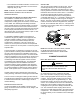
VENT/FLUE PIPE & COMBUSTION AIR PIPE
This manual refers to the pipe that discharges products
of combustion to the outdoors as the “vent” pipe or “ue”
pipe. The pipe that supplies air for combustion to the
furnace is referred to as the “intake” pipe or “combustion
air” pipe. A condensing gas furnace achieves its high
level of efciency by extracting almost all of the heat
from the products of combustion and cooling them to the
point where condensation takes place. Because of the
relatively low ue gas temperature and water condensation
requirements, PVC or ABS are typical venting and intake
pipe materials. In Canada ABS is not an approved vent
pipe material, but it is permissable to use as combustion air
pipe material.
In addition to PVC and ABS pipe and ttings, Innoue
®
by
Centrotherm Eco Systems and PolyPro
®
by M&G Duravent
are also approved vent and combustion air materials for
installations in the U.S.A. and Canada. Manufacturers
Installation instructions for these products must be
followed. These products have specic instructions for
installing, joining and terminating. Do not mix materials
or components of one manufacturer with materials or
components of another manufacturer.
All furnaces are manufactured with 2” vent / intake pipe
and connectors. For furnaces requiring installation of 3”
pipe, the transition from 2” to 3” should be done as close to
the furnace as practically possible.
This furnace must not be connected to Type B, BW, or
L vent or vent connector, and must not be vented into
any portion of a factory built or masonry chimney except
when used as a pathway for PVC as described later in
this section. Never common vent this appliance with
another appliance or use a vent which is used by a solid
fuel appliance. Do not use commercially available “no hub
connectors” other than those shipped with this product.
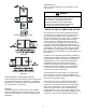
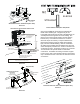
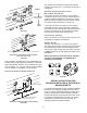
alternate Vent/flue locatIon
fIgure 3a
fIgure 3B
recoMMenDeD InstallatIon PosItIons
fIgure 3c
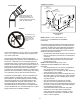
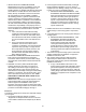
alternate electrIcal anD gas lIne connectIons
This furnace has provisions allowing for electrical and gas
line connectios through either side panel. In horizontal
applications the connections can be made either through
the “top”or “bottom” of the furnace.
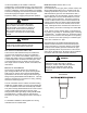
DraIn Pan
A drain pan must be provided if the furnace is installed
above a conditioned area. The drain pan must cover the
entire area under the furnace (and air conditioning coil if
applicable).