
GMVC9 GCVC9 Installation Instructions


45
THERMOSTAT MENU
If this furnace is installed with a communicating compatible
heat pump, the system is recognized as a dual fuel system.
The balance point temperature should be set via the thermo-
stat.
DIAGNOSTICS
Accessing the furnace’s diagnostic menu provides access to
the last six faults detected by the furnace. Faults are stored
most recent to least recent, Any consecutively repeated fault
is stored a maximum of three times. Example: A clogged
return air filter causes the furnace limit to trip repeatedly.
The control will only store this fault the first three consecu-
tive times the fault occurs. Navigate to the diagnostics menu
as described above in the thermostat installation manual.
NOTE: It is highly recommended that the fault history be
cleared when performing maintenance or servicing the fur-
nace.
NETWORKTROUBLESHOOTING
Communication is achieved by taking the difference between
two DC signals. The signals and transmission lines are re-
ferred to as “data 1” and “data 2.” The voltage difference
between data 1 and data 2 is typically 0.6 VDC.
The ComfortNet™ system is a fully communicating system, and
thus, constitutes a network. Occasionally the need to trouble-
shoot the network may arise. The integrated furnace control
has some on-board tools that may be used to troubleshoot the
network. These tools are: red communications LED, green re-
ceive (Rx) LED, and learn button.
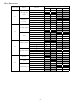
• Red communications LED – Indicates the status of the
network. The table below indicates the LED status
and the corresponding potential problem.
• Green receive LED – Indicates network traffic. The
table below indicates the LED status and the
corresponding potential problem.
• Learn button – Used to reset the network. Depress
the button for approximately 2 seconds to reset the
network.
SYSTEM TROUBLESHOOTING
NOTE: Refer to the instructions accompanying the ComfortNet
compatible outdoor AC/HP unit for troubleshooting information.
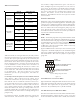
LED Description
Off Normal condition
Red
Communications
LED
1 Flash Communications
Failure
2 Flashes Out-of-box reset
Green Receive
LED
Off •Nopower
•Communications
error
1 Steady
Flash
No network
found
Rapid
Flashing
Normal network
traffc
On Solid Data 1/ Data 2
miss-wire
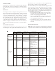
Possible Cause Corrective Action Comments
None None None
Communications
Failure
•Depress Learn Button
•Verify that bus BIAS and
TERM dipswitches are in
the ON position.
•Depress once quickly for
a power-up reset
•Depress and hold for 2
seconds for an out-of-box
reset
•Control power up
•Learn button depressed
None None
•No power to furnace
•Open fuse
•Communications error
•Check fuses and circuit
breakers; replace/reset
•Replace blown fuse
•Check for shorts in low
voltage wiring in furnace/
system
•Reset network by
depressing learn button
•Check data 1/ data 2
voltages
•Turn power OFF prior to
repair
•Broken/ disconnected
data wire(s)
•Furnace is installed
as a legacy/ traditional
system
•Check communications
wiring (data 1/ data 2
wires)
•Check wire connections
at terminal block
•Verify furnace installation
type (legacy/ traditional
or communicating) Check
data 1/ data 2 voltages
•Turn power OFF prior to
repair
•Verify wires at terminal
blocks are securely
twisted together prior to
inserting into terminal
block
•Verify data1 and data
voltages as described
above
Control is “talking” on
network as expected
None None
•Data 1 and data 2 wires
reversed at furnace,
thermostat, or CT™
compatible outdoor AC/
HP
•Short between data 1
and data 2 wires
•Short between data 1
or data 2 wires and R
(24VAC) or C (24VAC
common)
•Check communications
wiring (data 1/ data 2
wires)
•Check wire connections
at terminal block
•Check data 1/ data 2
voltages
•Turn power OFF prior to
repair
•Verify wires at terminal
blocks are securely
twisted together prior to
inserting into terminal
block
•Verify data1 and data
voltages as described
above