
Installation Instructions Comfort Bridge Models


35
R
C
G
Y
Optional
Optional
Optional if
feature
supported by
thermostat
INDOOR
BOARD TERMINAL
CONNECTIONS
OUTDOOR
BOARD TERMINAL
CONNECTIONS
OUTDOOR
TRANSFORMER
1
2
C
R
C
G
Y
1
2
C
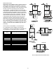
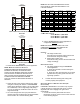
coMMunIcatIng two stage aIr conDItIoner or Heat
PuMP
fIgure 49
1
2
C
R
C
G
Y
Optional
Optional
Optional
INDOOR
BOARD TERMINAL
CONNECTIONS
OUTDOOR
BOARD TERMINAL
CONNECTIONS
1
2
C
R
C
G
Y
24 VAC
Thermostat
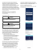
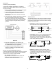
coMMunIcatIng InVerter aIr conDItIoner or Heat
PuMP
fIgure 50
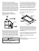
3. Download the CoolCloud HVAC phone application for
charging and to congure/test system operations.
note: wHen new VersIons of BluetootH
coMMunIcatIon software anD furnace control
software are aVaIlaBle, tHe PHone aPPlIcatIon
notIfIes tHe user. software uPDates are classIfIeD
as eItHer oPtIonal or ManDatorY anD InstalleD BY
usIng tHe PHone aPPlIcatIon. ensure all ManDatorY
software uPDates HaVe Been InstalleD. reVIew
notes for oPtIonal software uPDates anD Install If
necessarY.
note: If an e11 coDe exIsts for tHe InVerter sYsteM
IMMeDIatelY after lIne Voltage Is aPPlIeD (coDe sHown In tHe
coolclouD HVac PHone aPPlIcatIon or DIsPlaYeD on tHe
InVerter control), tHe sYsteM VerIfIcatIon test neeDs to Be
coMPleteD Before anY otHer oPeratIon. see tHe followIng
ProceDure.
This furnace is Bluetooth ready and functions with the
CoolCloud HVAC phone application designed to improve
the contractor’s setup / diagnostic experience. Users can
see specic model information, review active diagnostic
error codes, observe system status during operation,
make system menu adjustments, add site visit notes and
run system testing of all operational modes (heat / cool /
fan) directly from the phone. The phone application is also
capable of directly updating the furnace software anytime
updates are available. The application will automatically
notify the user if updates are available.
note: tHe software uPDate MaY take uP to 20
MInutes to coMPlete.
quIck start guIDe for coMMunIcatIng outDoor
unIts
EXTREMELY IMPORTANT: For all cooling calls the system
only requires a single Y input from the thermostat. For all
heating calls (including dual fuel applications) the system
only requires a single W input from the thermostat. Internal
algorithms will control all available cooling and heating
stages including dual fuel operation based on these inputs.
Any single-stage 24VAC thermostat can be used. For
proper operation the thermostat must be setup to control a
single-stage AC outdoor unit and to control a single stage
gas furnace. The control board does not accommodate an
O wire thermostat input (reversing valve signal). If a heat
pump is installed, the thermostat should be setup as stated
above. Setting the thermostat for the heat pump control or
multi stage control may result in incorrect performance.
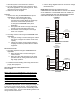
1. Connect all necessary thermostat wires to the
thermostat connector on the furnace control as
instructed by the applicable wiring diagrams shown in
this section.
2. Connect the 1 & 2 wires between the indoor and
outdoor unit for communicating operation.
Note: verify two stage outdoor units include a 24 VAC
transformer (for outdoor control board power) Two
stage outdoor units may not behave properly without
this 24 VAC transformer.