
Installation Instructions Comfort Bridge Models


34
This furnace is equipped with a blower door interlock
switch which interrupts unit voltage when the blower door
is opened for servicing. Do not defeat this switch.
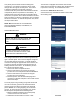
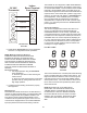
coolclouD™ HVac PHone aPPlIcatIon
Actual screens may look different based on the mobile
device being used.
fIgure 46
fIgure 47
fIgure 48
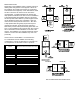
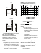
Line polarity must be observed when making eld
connections. Line voltage connections can be made
through either the right or left side panel. The furnace
is shipped congured for a right side electrical
connection with the junction box located inside the burner
compartment (blower compartment for downows). To
make electrical connections through the opposite side of
the furnace, the junction box must be relocated to the other
side of the burner (or blower) compartment prior to making
electrical connections. To relocate the junction box, follow
the steps shown below.
note: wIre routIng Must not to Interfere wItH
cIrculator Blower oPeratIon, fIlter reMoVal, or
routIne MaIntenance.
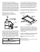
junctIon Box relocatIon
WARNING
eDges of sHeet Metal Holes MaY Be sHarP. use
gloVes as a PrecautIon wHen reMoVIng Hole
Plugs.
WARNING
to PreVent Personal InjurY or DeatH Due to
electrIc sHock, DIsconnect electrIcal Power
Before InstallIng or serVIcIng tHIs unIt.
Line voltage connections can be made through either the
right or left side panel. The furnace is shipped congured
for a left side electrical connection. To make electrical
connections through the opposite side of the furnace, the
junction box must be relocated to the right side prior to
making electrical connections. To relocate the junction
box, perform the following steps.
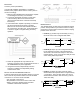
1. Remove the burner compartment door.
2. Remove and save the two screws securing the
junction box to the side panel.Horizontal Installations
3. Remove and save the two screws securing the
junction box to the side panel.
4. Relocate junction box and associated plugs and
grommets to opposite side panel. Secure with screws
removed in step 2.
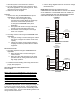
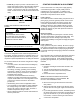
To ensure proper unit grounding, the ground wire should
run from the furnace ground screw located inside the
furnace junction box all the way back to the electrical
panel. NOTE: Do not use gas piping as an electrical
ground. To conrm proper unit grounding, turn off the
electrical power and perform the following check.
1. Measure resistance between the neutral (white)
connection and one of the burners.
2. Resistance should measure 10 ohms or less.