
Installation Instructions Comfort Bridge Models

22
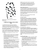
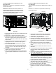
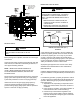
Hose #11
Hose #2
fIgure 25
1. Remove the clamps from both ends of the drain
hoses.
2. Remove the two screws holding the drain trap to the
blower deck.
3. Remove the trap and two hoses from the blower deck
4. Remove the two plugs from the right side of the
cabinet and install them in the blower deck.
5. (Draining the Vent Elbow) Locate hose #2 (factory
installed) and cut 1” away from the 45 degree bend,
discard the 45 degree section. Insert hose #2 from
outside the cabinet through the cabinet drain hole
nearest the top. Secure it to the barbed tting in the
elbow with a red clamp.
6. (Draining the Collector Box) Install the non-grommet
end of hose #11 from outside the cabinet in the
bottom drain hole. Install on collector box and secure
with a silver clamp.
7. Use two silver clamps and secure the hoses to drain
trap. The trap outlet faces the front of the furnace.
Secure the trap to the cabinet using two screws
removed in step 2 by inserting the two screws through
the large set of holes in the top mounting tabs of the
trap into the two predrilled holes in the side of the
cabinet.
8. Refer to Field Supplied Drain section for instructions
on eld supplied/nstalled drain on outlet of furnace
trap.
uPflow MoDel InstalleD HorIZontallY wItH left sIDe
Down
Minimum 5 ½” clearance is required for the drain trap
beneath the furnace.
*Also see Front Cover Pressure Switch Tube Location on
page 9.
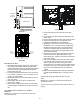
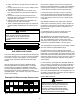
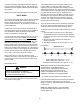
Side Cut-Out
12”
3”
Right side shown.
Acceptable
area for
drain hole.
fIgure 23
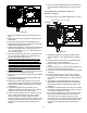
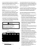
Installer selects right or left side drain
and installs this hose accordingly.
Hose #1
Hose #2
45 degree
barb-pipe
adapter
45 degree
barb-pipe
adapter
fIgure 24
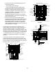
DraIn exItIng left sIDe
1. Install the 45 degree pipe / hose drain coupling from
the outside of the cabinet (barbed end goes in the
cabinet) through the hole in the left side of the cabinet
and secure with two eld supplied #8 self-tapping
screws (see Figure 23).
2. Locate the long drain hose #3 and cut at “B” line for a
17.5” cabinet; cut at line “C” for a 21” cabinet; do not
cut for a “D” width cabinet.
3. Install large end of hose #3 to trap outlet and secure
with 1.25” clamp.
4. Install smaller end of hose #3 on 45º elbow and
secure with 1” clamp.
5. Refer to Field Supplied Drain section for instructions
on eld supplied / installed drain on outlet of furnace
trap.
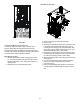
uPflow MoDel InstalleD HorIZontallY wItH rIgHt
sIDe Down
Minimum 5 ½” clearance is required for the drain trap
beneath the furnace.