
Installation Instructions Comfort Bridge Models

19
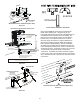
The vent/ue and combustion air pipes may terminate
vertically, as through a roof, or horizontally, as through an
outside wall.
Vent/Intake terMInatIons for InstallatIon of
MultIPle DIrect Vent furnaces
If more than one direct vent furnace is to be installed
vertically through a common roof top, maintain the same
minimum clearances between the exhaust vent and air
intake terminations of adjacent units as with the exhaust
vent and air intake terminations of a single unit.
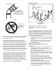
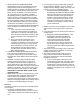
If more than one direct vent furnace is to be installed
horizontally through a common side wall, maintain the
clearances as in the following gure. Always terminate all
exhaust vent outlets at the same elevation and always
terminate all air intakes at the same elevation.
concentrIc Vent terMInatIon
Refer to the directions provided with the Concentric Vent
Kit (DCVK) for installation specications.
sIDe wall Vent kIt
This kit is to be used with 2” or 3” direct vent systems.
The vent kit must terminate outside the structure and may
be installed with the intake and exhaust pipes located
side-by-side or with one pipe above the other. These kits
are NOT intended for use with single pipe (indirect vent)
installations.
Refer to the directions furnished with the Side Wall
Vent Kit (p/n 0170K00000S or 0170K00001S) for
installation specications.
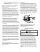
Vertical Installation
Horizontal Installation
fIgure 21
SPECIAL INSTRUCTIONS FOR
PRODUCTS INSTALLED IN THE STATE OF
MASSACHUSETTS
For all side wall horizontally vented gas fueled equipment
installed in every dwelling, building or structure used in
whole or in part for residential purposes, including those
owned or operated by the Commonwealth and where
the side wall exhaust vent termination is less than seven
(7) feet above nished grade in the area of the venting,
including but not limited to decks and porches, the
following requirements shall be satised:
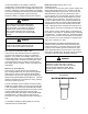
VENT/FLUE
TEE
COMBUSTION
AIR INTAKE.
DISTANCE BETWEEN
COMBUSTION AIR
INTAKE AND GRADE
DISTANCE BETWEEN
VENT AND GRADE
fIgure 18
Combustion Air Intake may also be snorkeled to obtain 12” min ground clearance.
90°
ELBOWS
3”-24” BETWEEN PIPES
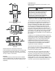
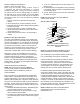
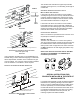
alternate Vent terMInatIon aBoVe antIcIPateD
snow leVel (Dual PIPe)
fIgure 19
If the combustion air intake pipe is to be installed above a
nished ceiling or other area where dripping of condensate
will be objectionable, insulation of the combustion air pipe
may be required. Use 1/2” thick closed cell foam insulation
such as Armaex™ or Insultube™ where required.
Vent/flue anD coMBustIon aIr PIPe terMInatIons
3” MIN
12” MIN TO GRADE OR HIGHEST
ANTICIPATED SNOW LEVEL
3”MIN
24”MAX
12” MIN SEPARATION
terMInatIon of MultIPle DIrect Vent furnaces
fIgure 20