
Installation Instructions

4
On the next stage 1 call for heat, furnace #1 is signaled to heat. This
sequence alternates on successive cycles balancing run times on the
furnaces.
If a stage 2 (W2) call for heat is received at any time W1 is activated the R-W
circuit of the non-firing furnace closes.
If both stages energize or deenergize simultaneously, operation is identical to
single stage operation above.
Two stage cooling is analogous to staged heating but activates the R-Y
circuits. The blowers will have a 65 second off delay in the cooling speed.
Hybrid Furnaces
When twinning hybrid furnaces, set the dip switch settings for both fur-
naces to the same setting.
Abnormal Conditions
If only one blower is sensed “ON” for more than four seconds while a thermo-
stat input is present, both furnaces will deenergize and the on-board LEDs are
activated. This lockout condition can be reset by turning the thermostat to the
OFF position or by turning the power OFF then back ON for both furnaces for
at least one second and returning to the desired function. If, when no thermo-
stat input is present, only a single blower is sensed, the blower circuits (R-G)
close to both furnaces for 155 seconds and then open. If the unbalanced
condition (one blower sensed), still exists, the sequence repeats.
Diagnostic LED Flash Sequence
The on-board LED activates with a blower failure on furnace 1, 2, or both. If the
furnace blower failure is on furnace 1, the LED will flash once with a two-
second off interval between flashes.
If the furnace blower failure is on furnace 2, the LED will flash twice with
a two-second off interval between flash sequences.
If the furnace blower failure is on both furnaces, the LED will flash three
times with a two-second off interval between flash sequences.
The REM FAULT SIGNAL output will flash continually in all fault code condi-
tions. The REM FAULT SIGNAL does not flash separate fault codes.
SECTION IV CHECKOUT AND REPAIRS
Startup Procedure
Refer to the Installation Instructions provided with the furnace for proper
operation and startup procedures after installing the twinning control. If
that information is not available, follow these instructions to ensure all
components function properly:
1. With the gas and thermostat off, turn ON power to the furnaces.
2. Turn the thermostat to a high setting and verify that both ignition
controls go through the operating sequence to a shutoff condition.
Note: The burners will not light because the gas is off.
3. Turn OFF the thermostat.
4. Turn ON the gas and purge gas lines of all air.
5. Check for gas leaks with a soap solution.
6. Turn the thermostat to a high setting and verify successful ignition and
a normal run condition for at least three minutes.
7. Do a leak check on all pipe joints downstream of the gas valve with a
soap solution.
8. Turn the thermostat down for at least 30 seconds and then back up
again. Verify successful ignition at least three times before leaving the
installation.
Repairs and Replacement
Do not attempt field repairs. Use only an exact or factory recommended
replacement control.
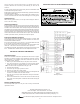
SECTION V POINT-TO-POINT WIRING DIAGRAM
e.
Figure 6
Twinning Controls
Goodman Manufacturing Company, L.P.
5151 San Felipe, Suite 500, Houston, TX 77056
www.daikincomfort.com, www.goodmanmfg.com and www.amana-hac.com
© 1998, 2004, 2006, 2011, 2013 Goodman Manufacturing Company, L.P.
®
is a trademark of Maytag Corporation and is used under license. All rights reserved.