
Installation Instructions

3
Continuous Fan Operation
Furnaces that are twinned using this kit cannot be setup for heating-
cooling-continuous fan speed operation. Furnace will operate at the same
continuous fan speed selected in the furnace control.
Condensate Disposal
When installing condensing furnaces, be sure to plan for adequate con-
densate drainage. This is especially important on counterflow installations.
Follow the condensate disposal piping directions shipped with the fur-
nace.
Unit Wiring
This kit allows the furnaces to be placed a maximum of five feet apart. Wire
routing between furnaces is the same for any type furnace being installed.
IMPORTANT NOTE: Any excess wires must be routed and secured to pre-
vent becoming entangled in either blower or damaged by either set of burners.
Kit Installation
1. Disconnect all electrical power to unit.
2. Find a location for mounting the twinning control. The side of the return
section of the furnace cabinet or on the return air duct would be adequate
locations.
NOTE: The control should be mounted in a location that allows ac-
cess to the terminals for wiring and servicing and keeps wire lengths
to a minimum.
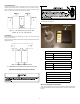
3. Drill three holes according to the following illustration (Figure 5).
4.50
7.50
3.00
6.01
7.48
0.75
Figure 5
Mounting Hole Locations
4. Using three #6 3/4-inch long screws (field-supplied), mount the twin-
ning control vertically with the connectors at the bottom as shown in
Figure 5. Do not over tighten the screws. DO NOT expose the control
to water or temperatures below -40°F or above 120°F.
5. Designate one of the furnaces as furnace #1 and the other as fur-
nace #2.
6. Connect furnace #1’s ignition control thermostat connectors: C, R, W,
Y, and G to an 18 gauge 5-wire thermostat cable.
7. Route the cable up through the blower deck and out the thermostat
wire hole on the side of the cabinet. Connect the wires to the correspond-
ing terminals on the furnace #1 section of the twinning control.
8. Repeat steps 6 and 7 for furnace #2.
Fan Sensor Wiring Installation
1. Route the two wire cable along the same path as the thermostat
wiring to the twinning control.
2. Connect the two wires to the corresponding FAN/LED SENSOR INPUTS
on the furnace #1 section of the twinning control. The cable can be cut to
a convenient length.
3. Locate the white neutral fan motor lead.
4. Remove the white neutral fan motor lead from the furnace board and
pass the wire through the hole in fan sensor #1.
5. Reconnect the white neutral fan motor lead to the furnace board in the
same location as it was removed.
6. Repeat steps 1 through 5 for furnace #2.
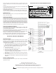
Thermostat Wiring Installation
Important Note: The system thermostat that controls the conditioned space
should not have a current draw higher than 25 milliamps.
1. The control allows the use of a two stage heating and cooling ther-
mostat. If a single stage heating or cooling thermostat is used the W1
and W2 (1 stage heating) or Y1 and Y2 (1 stage cooling) must be
jumped together. For thermostats that require a “common” connec-
tion a “C” terminal is provided.
2. The heat anticipator in the room thermostat must be correctly adjusted
to obtain the proper number of heating cycles per hour and to prevent
the room temperature from “overshooting” the room thermostat setting.
Heat anticipator must be set at 0.16 amps.
SECTION III SEQUENCE OF OPERATION
Single Stage Thermostat
On a system call for heat a relay closes both blower (R-G) circuits, powering
the blowers of both furnaces (continuous fan speed). One second later, relays
close the heating (R-W) circuits of both furnaces. In 30 or 45 seconds after the
furnaces fire, the blowers will switch to the heating speed. When the call for
heat is satisfied at the thermostat, both (R-W) circuits will immediately open.
Following approximately a 155 second delay, the fan (R-G) circuits will open.
For cooling operation, the sequence is identical but with the R-Y circuits acti-
vated.
NOTE: In the heating mode, if the furnace control module blower off timing
is longer than the Twinning Control's 155 seconds, the blower(s) will con-
tinue to operate in the heating speed until the furnace control module blower
off delay is satisfied.
Two-Stage Thermostat
On a first stage call for heat, a relay will close both blower (R-G) circuits as
in the single stage operation. One second later, a relay will close the heating
circuit (R-W) of furnace #2 only. In 30 or 45 seconds after the furnaces light,
the blower of furnace #2 will switch to the heating speed. When the call for
heat is satisfied, the (R-W) circuit will open and the 155 second Twinning
Control fan off delay begins. The furnace #2 blower will operate in the heating
speed until the furnace control module blower off delay is satisfied, then the
blower will switch to the continuous fan speed.
NOTE: If the furnace control blower off delay is longer than the 155 second
Twinning Control off delay, the Twinning Control will turn off the blowers. The
blower for furnace #1 will shut off, and since the blower on furnace #2 is still
running, the blower for furnace #1 will reenergize in the continuous fan speed.
This process will continue until the furnace control blower off timing is satisfied
and both blowers are running in the continuous fan speed. The Twinning Control
will then simultaneously turn off both blowers. To prevent this operation, set
both furnace's heat off delay time to 150 seconds or less, provided both are
set to the same time.