
DFK Installation Instructions

DESCRIPTION
The DFK Downflow Kit is applied to the bottom of the drain
pan to prevent possible condensation from forming on the
drain pan in the downflow application. They are used with the
ARUF**14**, ARPT**14**, ASPT**14**, ASUF**14** and
AVPTC**14* air handlers.
DFK-B
Downflow Kit
DFK-C
Downflow Kit
DFK-D
Downflow Kit
ARUF18B14** ARUF36C14** ARUF48D14**
ARUF24B14** ARUF30C14** ARUF60D14**
ARUF30B14** ARUF42C14** ARPT36D14**
ARPT18B14** ARPT36C14** ARPT42D14**
ARPT24B14** ASUF39C14** ARPT48D14**
ARPT30B14** ASUF49C14** ARPT60D14**
ASUF29B14** ASPT30C14** ASUF59D14**
ASPT24B14** ASPT36C14** ASPT42D14**
AVPTC24B14** AVPTC30C14** ASPT48D14**
AVPTC36C14** ASPT60D14**
AVPTC42D14**
AVPTC48D14**
AVPTC60D14**
MODEL LIST FOR DOWNFLOW KITS
KIT INSTRUCTIONS:
1. To ensure proper adhesion, clean all surfaces of drain
pan so they are all clear of oil, dust and moisture.
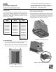
2. Identify sides A, B, C and D of the insulation and drain
pan as shown in Figure 1. (Side D is wider than side B.)
C
B
A
D
FIGURE 1 - Bottom View of Coil
© 2013 Goodman Manufacturing Company, L.P.
5151 San Felipe, Suite 500, Houston, TX 77056
www.goodmanmfg.com -or- www.amana-hac.com
P/N: IOG-7001 Date: March 2013
3. Remove side A of insulation backing. Do not remove entire
piece of backing from insulation.
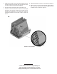
4. Line up side A of the insulation with side A of the drain pan
and firmly attach the insulation to the drain pan with roughly
a ¼” portion of the insulation folded over the edge as
shown in Figures 2 and 3. Fold the insulation over to cover
the inside portion of the drain pan on side A.
C
B
A
D
FIGURE 2 - Rolled Edge Location
D
.
2
5
C
.25
1.50
FIGURE 3 - Rolled Edge Location Detail
DFK
DOWNFLOW KIT
INSTALLATION INSTRUCTIONS