
CSCF R-22 Service Manual

SERVICING
58
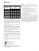
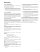
S-105A PISTON KIT CHART FOR ASC13,
GSC13, VSC13, GSC14, ASH13, GSH13,
VSH14, GSH14 UNITS
Air Conditioners
Orifice
Size
Heat Pumps
Orifice
Size
GSC130181A* / B* / C* .055
G/VSH130181A* .052
VSC130181A* / B* .055
GSH130181B* .055
G/VSC130241A*
.059
G/VSH130191A* .052
GSC130241C* G/VSH130241A* .061
AC30, ACNF24
.059
GSH130241B* .061
AWB24/AWUF24
.059
G/VSH130251A* .061
# All other ARI Matches .061 G/VSH130301A* .068
G/VSC130301A* / D* GSH130301B* .070
VSC130301B* G/VSH130311A* .065
GSC130303A* G/VSH130361A* .073
AC36, ACNF30
.065
GSH1303613A*/1B* .082
AWB36, AWUF36
.068
G/VSH130421A* .082
# All other ARI Matches
.065
G/VSH130481A* .084
G/VSC130361A* GSH1304813A*/ 4A* .084
GSC130363A* / B*
.071
G/VSH130601A* .093
AWB36, AWUF36
.071
GSH1306013A*/ 4A* .093
# All other ARI Matches
.074
ASH130181A* .052
GSC130361B* / F* .071 ASH130241A* .062
VSC130361B* .071
ASH130301A* .065
G/VSC130421A* .078
ASH130361A* .073
GSC130421B* .084 ASH130421A* .082
G/VSC130481A .082
ASH130481A* .084
GSC130483A*/ 4A* .082
ASH130601A* .093
GSC130481B*/3B*/ 4B* .088 GSH140361A* .076
G/VSC130601A* .093 GSH140421A* .078
GSC130601C*/3B*/4B* .093 GSH140481A* .088
GSC130603A*/ 4A* .093
ASC130181A* .055
ASC130241A* .061
ASC130301A* .065
ASC130361A* .071
ASC130421A* .078
ASC130481A* .082
ASC130601A* .093
GSC140181A* .053
GSC140241A* .061
GSC140301A* .067
GSC140361A* .074
GSC140421A* .078
GSC140481A* .084
GSC140601A* .096
GSC140181B* .055
GSC140241B* .062
GSC140301B* .067
GSC140361B* .073
GSC140421B* .080
S-105B THERMOSTATIC EXPANSION VALVE
The expansion valve is designed to control the rate of liquid
refrigerant flow into an evaporator coil in exact proportion to
the rate of evaporation of the refrigerant in the coil. The amount
of refrigerant entering the coil is regulated since the valve
responds to temperature of the refrigerant gas leaving the coil
(feeler bulb contact) and the pressure of the refrigerant in the
coil. This regulation of the flow prevents the return of liquid
refrigerant to the compressor.
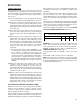
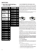
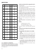
The illustration below shows typical heat pump TXV/check
valve operation in the heating and cooling modes.
COOLING HEATING
THERMOSTATIC EXPANSION VALVES (TXV VALVES)
Goodman
®
brand TXV valves contain an internal check valve
thus eliminating the need for an external check valve and
bypass loop. The three forces which govern the operation of
the valve are: (1) the pressure created in the power assembly
by the feeler bulb, (2) evaporator pressure, and (3) the
equivalent pressure of the superheat spring in the valve. 0%
bleed type expansion valves are used on indoor and outdoor
coils. The 0% bleed valve will not allow the system pressures
(High and Low side) to equalize during the shut down period.
The TXV internal check valve will hold a pressure differential
of 100 PSID.
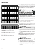
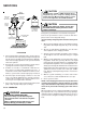
The bulb must be securely fastened with two straps to a clean
straight section of the suction line. Application of the bulb to
a horizontal run of line is preferred. If a vertical installation
cannot be avoided, the bulb must be mounted so that the
capillary tubing comes out at the top.
THE VALVES PROVIDED BY GOODMAN
®
BRAND ARE
DESIGNED TO MEET THE SPECIFICATION REQUIRE-
MENTS FOR OPTIMUM PRODUCT OPERATION. DO NOT
USE SUBSTITUTES.
S-106 OVERFEEDING
Overfeeding by the expansion valve results in high suction
pressure, cold suction line, and possible liquid slugging of the
compressor.
If these symptoms are observed:
1. Check for an overcharged unit by referring to the cooling
performance charts in the servicing section.
2. Check the operation of the power element in the valve as
explained in S-110 Checking Expansion Valve Operation.
3. Check for restricted or plugged equalizer tube.