
CSCF R-22 Service Manual

SERVICING
51
4.4 In order to make sure the blower is running when heat is
on, the normally closed contacts on the EBTDR will
power the blower motor if no G signal is received.
4.5 There may be delay on activation or deactivating heater
elements.
5.0 Defrost Operation
On heat pump units, when the room thermostat is set to the
heating mode, the reversing valve is not energized. As long
as the thermostat is set for heating, the reversing valve will be
in the de-energized position for heating except during a
defrost cycle.
5.1 The heat pump will be on and operating in the heating
mode as described the Heating Operation in section 4.
5.2 The defrost control in the heat pump unit checks to see
if a defrost is needed every 30, 60 or 90 accumulated of
compressor runtime minutes of heat pump operation
depending on the selectable setting by monitoring the
state of the defrost thermostat attached to the outdoor
coil.
5.3 If the temperature of the outdoor coil is low enough to
cause the defrost thermostat to be closed when the
defrost board checks it, and if accumulated compressor
runtime of 30, 60 or 90 minutes expires the board will
initiate a defrost cycle.
5.4 When a defrost cycle is initiated, the contacts of the
HVDR relay on the defrost board open and turns off the
outdoor fan. The contacts of the LVDR relay on the
defrost board closes and supplies 24Vac to “O” and “W2”.
The reversing valve is energized and 1st stage of elec-
tronic heat is energized. The unit will continue to run in
this mode until the defrost cycle is completed, or maxi-
mum defrost time of 12 minutes expires.
a. For models with defrost control PCBDM133, a 30
second compressor delay at defrost initiation/termina-
tion is optional. As shipped from the factory, the
control is set for the delay (“DLY”), which will turn the
compressor off for 30 seconds at entering and exiting
defrost operation while the reversing valve shifts to/
from the cooling mode position. To bypass the delay,
which typically reduces sound levels during defrost
mode, change the pin settings from “DLY” to “NORM”.
5.5 When the defrost cycle is terminated, the contacts of the
HVDR relay will close to start the outdoor fan and the
contacts of the LVDR relay will open and turn off the
reversing valve and electric heater(s). The unit will now be
back in a normal heating mode with a heat pump demand
for heating as described in the Heating Operation in
section 4. See section 5.4a.
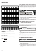
S-41 AEP* & MBE WITH SINGLE STAGE CON-
DENSERS
AEP* & MBE ELECTRONIC BLOWER TIME DELAY RELAY
SEQUENCE OF OPERATION
This document covers the basic sequence of operation for a
typical application with a mercury bulb thermostat. When a
digital/electronic thermostat is used, the on/off staging of the
auxiliary heat will vary. Refer to the installation instructions
and wiring diagrams provided with the MBE for specific wiring
connections, dip switch settings and system configuration.
AEP* & MBE WITH SINGLE STAGE CONDENSERS
When used with a single stage condenser, dip switch #4
must be set to the on position on the VSTB inside the MBE.
The “Y” output from the indoor thermostat must be connected
to the yellow wire labeled “Y/Y2” inside the wire bundle
marked “Thermostat” and the yellow wire labeled “Y/Y2”
inside the wire bundle marked “Outdoor Unit” must be
connected to “Y” at the condenser. The orange jumper wire
from terminal “Y1” to terminal “O” on the VSTB inside the
MBE must remain connected.
1.0 Cooling Operation
1.1 On a demand for cooling, the room thermostat energizes
“G” and “Y” and 24Vac is supplied to “G” and “Y/Y2” of the
MBE unit. The VSTB inside the MBE will turn on the
blower motor and the motor will ramp up to the speed
programmed in the motor based on the settings for dip
switch 5 and 6. The VSTB will supply 24Vac to “Y” at the
condenser and the compressor and condenser are turned
on.
1.2 When the cooling demand is satisfied, the room thermo-
stat removes the 24Vac from “G” and “Y”. The MBEand
AEP* remove the 24Vac from “Y’ at the condenser and the
compressor and condenser fan are turned off. The blower
motor will ramp down to a complete stop based on the
time and rate programmed in the motor.
2.0 Heating Operation
2.1 On a demand for heat, the room thermostat energizes
“W1” and 24Vac is supplied to terminal “E/W1” of the
VSTB inside the MBEand AEP* units. The VSTB will turn
on the blower motor and the motor will ramp up to the
speed programmed in the motor based on the settings for
dip switch 1 and 2. The VSTB will supply 24Vac to heat
sequencer HR1 on the electric heater assembly.
2.2 HR1 contacts M1 and M2 will close within 10 to 20
seconds and turn on heater element #1. At the same
time, if the heater assembly contains a second heater
element, HR1 will contain a second set of contacts, M3
and M4, which will close and turn on heater element #2.
Note: If more than two heater elements are on the heater
assembly, it will contain a second heat sequencer, HR2,
which will control the 3
rd
and 4
th
heater elements if
available. For the 3
rd
and 4
th
heater elements to
operate on a second stage heat demand, the PJ4
jumper on the VSTB inside the MBE and AEP* must
be cut. With the PJ4 jumper cut, the VSTB will run the
blower motor on low speed on a “W1” only demand. If the
first stage heat demand, “W1” cannot be satisfied by the
heat pump, the temperature indoors will continue to drop.
The room thermostat will then energize “W2” and 24Vac
will be supplied to HR2 on the heater assembly and the
blower motor will change to high speed. When the “W2”
demand is satisfied, the room thermostat will remove the