
CSCF R-22 Service Manual

SERVICING
50
S-40 AR*F & MBR ELECTRONIC BLOWERS
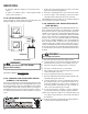
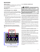
TIME DELAY RELAY
The MBR contains an Electronic Blower Time Delay Relay
board, PCBFM103. This board provides on/off time delays for
the blower motor in cooling and heat pump heating demands
when “G” is energized.
During a cooling or heat pump heating demand, 24Vac is
supplied to terminal “G” of the EBTDR to turn on the blower
motor. The EBTDR initiates a 7 second delay on and then
energizes it’s onboard relay. The relay on the EBTDR board
closes it’s normally open contacts and supplies power to the
blower motor. When the “G” input is removed, the EBTDR
initiates a 65 second delay off. When the 65 seconds delay
expires the onboard relay is de-energized and it’s contacts
open and remove power from the blower motor.
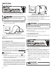
During an electric heat only demand, “W1” is energized but
“G” is not. The blower motor is connected to the normally
closed contacts of the relay on the EBTDR board. The other
side of this set of contacts is connected to the heater
assembly that provides power to the 1st stage of heat. When
“W1” is energized, and the blower motor is powered through
the normally closed contacts on the relay of the EBTDR.
There may be delay on activation or deactivating heater
elements.
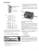
The EBTDR also contains a speedup terminal to reduce the
delays during troubleshooting of the unit. When this terminal
is shorted to the common terminal, “C”, on the EBTDR board,
the delay ON time is reduced to 3 seconds and the delay OFF
time is reduced to 5 second.
Two additional terminals, M1 and M2, are on the EBTDR
board. These terminals are used to connect the unused leads
from the blower motor and have no affect on the board’s
operation.
SEQUENCE OF OPERATION
This document covers the basic sequence of operation for a
typical application with a mercury bulb thermostat. When a
digital/electronic thermostat is used, the on/off staging of the
auxiliary heat will vary. Refer to the installation instruc-
tions and wiring diagrams provided with the MBR and
AR*F for specific wiring connections and system con-
figuration.
AR*F & MBR
WITH SINGLE STAGE CONDENSERS
1.0 Cooling Operation
1.1 On a demand for cooling, the room thermostat energizes
“G” and “Y” and 24Vac is supplied to “Y” at the condensing
unit and the “G” terminal on the EBTDR board.
1.2 The compressor and condenser fan are turned on and
after a 7 second on delay, the relay on the EBTDR board
is energized and the blower motor starts.
1.3 When the cooling demand “Y” is satisfied, the room
thermostat removes the 24Vac from “G” and “Y”.
1.4 The compressor and condenser fan are turned off and after
a 65 second delay off, the relay on the EBTDR board is de-
energized and the blower is turned off.
2.0 Heating Operation
2.1 On a demand for heat, the room thermostat energizes
"W1" and 24 Vac is supplied to turn on the 1st stage of
heat. If W2 is energized, then the 2nd stage will be turned
on. This may be turning on contactor(s) or sequencer(s).
2.2 In order to make sure the blower is running when heat is
on, the normally closed contacts on the EBTDR will
power motor the blower motor if no G signal is received.
AR*F & MBR
WITH SINGLE STAGE HEAT PUMPS
3.0 Cooling Operation
On heat pump units, when the room thermostat set to the
cooling mode, 24Vac is supplied to “O” which energizes the
reversing valve. As long as the thermostat is set for cooling,
the reversing valve will be in the energized position for cooling.
3.1 On a demand for cooling, the room thermostat energizes
“G” and “Y” and 24Vac is supplied to “Y” at the heat pump
and the “G” terminal on the EBTDR board.
3.2 The heat pump turned on in the cooling mode and after a
7 second on delay, the relay on the EBTDR board is
energized and the blower motor starts.
3.3 When the cooling demand is satisfied, the room thermo-
stat removes the 24Vac from “G” and “Y”.
3.4 The heat pump is turned off and after a 65 second delay
off, the relay on the EBTDR board is de-energized and the
blower motor is turned off.
4.0 Heating Operation
On heat pump units, when the room thermostat set to the
heating mode, the reversing valve is not energized. As long
as the thermostat is set for heating, the reversing valve will be
in the de-energized position for heating except during a
defrost cycle. Some installations may use one or more
outdoor thermostats to restrict the amount of electric heat
that is available above a preset ambient temperature. Use of
optional controls such as these can change the operation of
the electric heaters during the heating mode. This sequence
of operation does not cover those applications.
4.1 On a demand for first stage of heat with heat pump units,
the room thermostat energizes “G” and “Y” and 24Vac is
supplied to “Y” at the heat pump unit and the “G” terminal
on the EBTDR board. The heat pump is turned on in the
heating mode and the blower motor starts after a 7 second
on delay.
4.2 If the first stage of heat is not satisfied by the heat
pump,then some thermostats may call fo r2nd or 3rd
stage of heat (1st and 2nd stage of electric heat).
4.3 On a demand for heat, the room thermostat energizes
"W1" and 24Vac is supplied to turn on the 1st stage of
heat. If W2 is energized, then the 2nd stage will be turned
on. This may be turning on contactor(s) or sequaencer(s).