
CSCF R-22 Service Manual

SERVICING
38
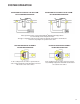
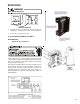
S-6 CHECKING TIME DELAY RELAY
Time delay relays are used in some of the blower cabinets
to improve efficiency by delaying the blower off time. Time
delays are also used in electric heaters to sequence in
multiple electric heaters.
WARNING
Disconnect ALL power before servicing.
1. Tag and disconnect all wires from male spade connec-
tions of relay.
2. Using an ohmmeter, measure the resistance across
terminals H1 and H2. Should read approximately 150
ohms.
3. Using an ohmmeter, check for continuity across termi-
nals 3 and 1, and 4 and 5.
4. Apply 24 volts to terminals H1 and H2. Check for
continuity across other terminals - should test continu-
ous. If not as above - replace.
NOTE: The time delay for the contacts to make will be
approximately 20 to 50 seconds and to open after the coil
is de-energized is approximately 40 to 90 seconds.
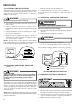
OHMMETER
TESTING COIL CIRCUIT
S-7 CHECKING CONTACTOR AND/OR RE-
LAYS
WARNING
HIGH VOLTAGE!
Disconnect ALL power before servicing or installing.
Multiple power sources may be present. Failure to do
so may cause property damage, personal injury
or death.
The compressor contactor and other relay holding coils are
wired into the low or line voltage circuits. When the control
circuit is energized, the coil pulls in the normally open
contacts or opens the normally closed contacts. When the
coil is de-energized, springs return the contacts to their
normal position.
NOTE: Most single phase contactors break only one side
of the line (L1), leaving 115 volts to ground present at most
internal components.
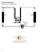
1. Remove the leads from the holding coil.
2. Using an ohmmeter, test across the coil terminals.
If the coil does not test continuous, replace the relay or
contactor.
S-8 CHECKING CONTACTOR CONTACTS
DISCONNECT ELECTRICAL POWER SUPPLY.
WARNING
Disconnect Electrical Power Supply:
1. Disconnect the wire leads from the terminal (T) side of the
contactor.
2. With power ON, energize the contactor.
WARNING
Line Voltage now present.
3. Using a voltmeter, test across terminals.
A. L2 - T1 - No voltage indicates CC1 contacts open.
If a no voltage reading is obtained - replace the contactor.
VOLT/OHM
METER
T1
T2
L1L2
CC
Ohmmeter for testing holding coil
Voltmeter for testing contacts
TESTING COMPRESSOR CONTACTOR
S-9 CHECKING FAN RELAY CONTACTS
1. Disconnect wire leads from terminals 2 and 4 of Fan Relay
Cooling and 2 and 4, 5 and 6 of Fan Relay Heating.
2. Using an ohmmeter, test between 2 and 4 - should read
open. Test between 5 and 4 - should read continuous.
3. With power ON, energize the relays.