
CSCF R-22 Service Manual

SERVICING
37
4. Check the continuity of the thermostat and wiring. Repair
or replace as necessary.
Resistance Heaters
1
. Set room thermostat setpoint to a higher temperature
than room temperature to assure both stages call for
heat.
2. With voltmeter, check for 24 volts at each heater relay.
3. No voltage indicates the trouble is in the thermostat or
wiring.
4. Check the continuity of the thermostat and wiring. Repair
or replace as necessary.
NOTE: Consideration must be given to how the heaters are
wired (O.D.T. and etc.). Also safety devices must be checked
for continuity.
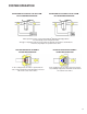
S-3B COOLING ANTICIPATOR
The cooling anticipator is a small heater (resistor) in the
thermostat. During the "off" cycle, it heats the bimetal
element helping the thermostat call for the next cooling cycle.
This prevents the room temperature from rising too high
before the system is restarted. A properly sized anticipator
should maintain room temperature within 1 1/2 to 2 degree
range.
The anticipator is supplied in the thermostat and is not to be
replaced. If the anticipator should fail for any reason, the
thermostat must be changed.
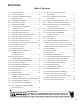
S-3C HEATING ANTICIPATOR
The heating anticipator is a wire wound adjustable heater
which is energized during the "ON" cycle to help prevent
overheating of the conditioned space.
The anticipator is a part of the thermostat and if it should fail
for any reason, the thermostat must be replaced. See the
following tables for recommended heater anticipator setting
in accordance to the number of electric heaters installed.
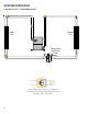
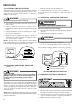
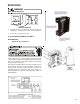
S-4 CHECKING TRANSFORMER AND CON-
TROL CIRCUIT
A step-down transformer (208/240 volt primary to 24 volt sec-
ondary) is provided with each indoor unit. This allows ample
capacity for use with resistance heaters. The outdoor sec-
tions do not contain a transformer.
WARNING
Disconnect ALL power before servicing.
1. Remove control panel cover, or etc., to gain access to
transformer.
With power ON:
WARNING
Line Voltage now present.
2. Using a voltmeter, check voltage across secondary volt-
age side of transformer (R to C).
3. No voltage indicates faulty transformer, bad wiring, or bad
splices.
4. Check transformer primary voltage at incoming line volt-
age connections and/or splices.
5 If line voltage available at primary voltage side of trans-
former and wiring and splices good, transformer is
inoperative. Replace.
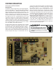
S-5 CHECKING CYCLE PROTECTOR
Some models feature a solid state, delay-on make after
break time delay relay installed in the low voltage circuit.
This control is used to prevent short cycling of the compres-
sor under certain operating conditions.
The component is normally closed (R
1
to Y
1
). A power
interruption will break circuit (R
1
to Y
1
) for approximately
three minutes before resetting.
1. Remove wire from Y
1
terminal.
2. Wait for approximately four (4) minutes if machine was
running.
With power ON:
WARNING
Line Voltage now present.
1. Apply 24 VAC to terminals R
1
and R
2
.
2. Should read 24 VAC at terminals Y
1
and Y
2
.
3. Remove 24 VAC at terminals R
1
and R
2
.
4. Should read 0 VAC at Y
1
and Y
2
.
5. Reapply 24 VAC to R1 and R2 - within approximately
three (3) to four (4) minutes should read 24 VAC at Y
1
and
Y
2
.
If not as above - replace relay.