
CSCF R-22 Service Manual

PRODUCT DESIGN
26
This section gives a basic description of cooling unit opera-
tion, its various components and their basic operation. En-
sure your system is properly sized for heat gain and loss
according to methods of the Air Conditioning Contractors
Association (ACCA) or equivalent.
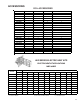
CONDENSING UNIT
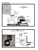
These units are designed for free air discharge. Condensed
air is pulled through the condenser coil by a direct drive
propeller fan and then discharged from the cabinet top. The
unit requires no additional resistance (i.e. duct work) and
should not be added.
The GSH13, GSH14, ASH13 and VSH13 Heat Pump con-
densing units are designed for 208-230 dual voltage single
phase applications. The GSH13 3 ton model is available in
230V, 3 phase applications. The GSH13 4 and 5 ton models
are available for 230V, 3-phase and 460V, 3-phase applica-
tions.
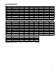
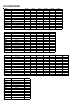
The units range in size from 1.5 to 5-ton and have a rating of
13 and 14 SEER. SEER efficiency is dependent upon the unit
and its components. Refer to the "Technical Information"
manual of the unit you are servicing for further details.
The GSC13, GSC14 and ASC13 and VSC13 Condensing
Units are made in 1.5 through 5 ton sizes. They are designed
for 208-240 volt single phase applications. The GSC13 3 ton
model is available in 230V, 3 phase applications. The GSC13
4 and 5 ton models are available for 230V, 3-phase and 460V,
3-phase applications.
Suction and Liquid Line Connections
All units come equipped with suction and liquid valves designed
for connection to refrigerant-type copper. Front seating valves
are factory-installed to accept the field-run copper. The total
refrigerant charge needed for a normal operation is also
factory-installed. For additional refrigerant line set information,
refer to the "Technical Information" manual of the unit you are
servicing.
Compressors
GSC13, VSC13, GSH13 and VSH13 use a mix of reciprocat-
ing and scroll compressors, except for the VSC130181AA/BA
which uses a rotary compressor. The ASC13 and ASH13 use
the Copeland Scroll
®
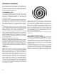
Compressor. There are a number of
design characteristics which differentiate the scroll com-
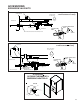
pressor from the reciprocating compressor. One is the scroll.
A scroll is an involute spiral which, when matched with a
mating scroll form, generates a series of crescent-shaped gas
pockets between the members (see following illustration).
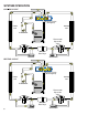
During compression, one scroll remains stationary while the
other form orbits. This motion causes the resulting gas pocket
to compress and push toward the center of the scrolls. When
the center is reached, the gas is discharged out a port located
at the compressor center.
GSC130361D* and GSC130481AG use Bristol
®
BENCH-
MARK™ compressors, the most advanced compressors in
the industry today. The BENCHMARK™ reciprocating com-
pressor can be recognized by a “J” in the fourth character of the
compressor model number. Innovative mechanical design and
gas management make the BENCHMARK™ compressor very
efficient and remarkably quiet. The sound content (frequency)
delivers exceptional acoustical characteristics and the virtu-
ally round housing design is compact and also helps to reduce
the overall sound and vibration.
GSC130181BA and GSC130181CA use Panasonic
®
rotary
compressors.
COILS AND BLOWER COILS
MBR/MBE blower cabinets are designed to be used as a two-
piece blower and coil combination. MBR/MBE blower sections
can be attached to cased evaporator coil. This two-piece
arrangement allows for a variety of mix-matching possibilities
providing greater flexibility. The MBE blower cabinet uses a
variable speed motor that maintains a constant airflow with a
higher duct static.
It is approved for applications with cooling coils of up to 0.8
inches W.C. external static pressure and includes a feature
that allows airflow to be changed by +15%. The MBR blower
cabinet uses a PSC motor. It is approved for applications with
cooling coils of up to 0.5 inches W.C. external static pressure.