
CSCF Installation Manual

2
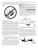
If the coil and furnace combination are not similar in depth and
width, a field-supplied transition must be used to center the
furnace and coil openings (see Figure 1 above). The coil must
not be installed directly onto the furnace outlet (see Figure 2
below).
COIL
FURNACE
PLENUM
DUCT BOARD, SHEET
METAL OR OTHER
FILLER MATERIAL
Figure 2
Condensate Drain Piping
In all cooling applications, a secondary drain pan should be
provided by the installer and placed under the entire unit with a
separate drain line properly sloped and terminated in an area
visible to the owner. This secondary drain pan can provide ex-
tra protection to the area under the unit should the primary
drain plug up and overflow. As expressed in our product war-
ranty, we will not be liable for any damages, structural or other-
wise due to the failure to follow this installation requirement.
The coil drain pan has a primary and an optional secondary
drain with 3/4" NPT female connections. The connectors re-
quired can be 3/4" NPT male either PVC or metal pipe and
should be hand tightened to a torque of no more than 37 in-lbs.
to prevent damage to the drain pan connection. An insertion
depth between .355 to .485 inches (3-5 turns) should be ex-
pected at this torque. If using a copper drain line, solder a
short piece of pipe to the connector before installing a drain
fitting. DO NOT over torque the 3/4” copper connector to the
plastic drain connection.
1. Ensure drain pan hole is NOT obstructed.
2. To prevent potential sweating and dripping on to finished
space, it may be necessary to insulate the condensate
drain line located inside the building. Use Armaflex
®
or
similar material.
A Secondary Condensate Drain Connection has been provided
for areas where the building codes require it. Pitch the drain
line 1/4" per foot to provide free drainage. Insulate drain lines
(primary and secondary) located inside the building to prevent
sweating. Install a condensate trap to ensure proper drainage.
If the secondary line is required, run the line separately from
the primary drain and end it where it can be easily seen.
NOTE: Water coming from this line means the coil primary
drain is plugged and needs clearing.
If secondary drain is not installed, the secondary access
must be plugged.
CAUTION
NOTE: Trapped lines are required by many local codes. In the
absence of any prevailing local codes, please refer to the
requirements listed in the Uniform Mechanical Building Code.
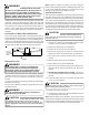
A drain trap in a draw-through application prevents air from
being drawn back through the drain line during fan operation
thus preventing condensate from draining, and if connected to
a sewer line to prevent sewer gases from being drawn into the
airstream during blower operation. In a blow-through applica-
tion the drain trap prevents conditioned air from escaping. It is
permissible in this application to use a shallow trap design
sometimes referred to as a running trap.
Cased Coil
3" MIN.
POSITIVE LIQUID SEAL
REQUIRED AT TRAP
Drain
Connection
2" MIN.
Figure 3
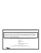
The depth of a running trap should be either 1" or a depth that
permits unrestricted condensate drainage without excessive
air discharge.
Field experience has shown condensate drain traps with an
open vertical Tee between the air handler and the condensate
drain trap can improve condensate drainage in some applica-
tions, but may cause excessive air discharge out of the open
Tee. The manufacturer does not prohibit this type of drain but
we also do not recommend it due to the resulting air leakage.
Regardless of the condensate drain design used, it is the
installer’s responsibility to ensure the condensate drain sys-
tem is of sufficient design to ensure proper condensate re-
moval from the coil drain pan.
PITCH
TOWARDS
DRAIN
1” MIN
TRAP
CONDENSATE
DRAIN CONN.
CONNECT DRAIN
SAME SIZE AS ON
UNIT OR LARGER
Figure 4