
CSCF Evaporator Installation Instructions

3
Tee. The manufacturer does not prohibit this type of drain but
we also do not recommend it due to the resulting air leakage.
Regardless of the condensate drain design used, it is the
installer’s responsibility to ensure the condensate drain sys-
tem is of sufficient design to ensure proper condensate re-
moval from the coil drain pan.
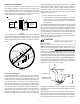
PITCH
TOWARDS
DRAIN
1” MIN
TRAP
CONDENSATE
DRAIN CONN.
CONNECT DRAIN
SAME SIZE AS ON
UNIT OR LARGER
Figure 4
Do not use the coil pan shipped with the unit on OIL
furnaces or any application where the temperature of
the drain pan may exceed 300ºF. A field fabricated
metal drain pan should be used for these type of appl-
ications. Failure to follow this warning may result in
property damage and/or personal injury.
WARNING
Install a trap in the drain line below the bottom of the drain pan
(required). If using a copper drain line, solder a short piece of
pipe to the connector before installing a drain fitting. DO NOT
over torque the 3/4” copper connector to the plastic drain con-
nection. Using a wet rag or heatsink material on the short
piece to protect plastic drain pan, complete the drain line in-
stallation.
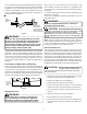
Horizontal Coil Water Blow-Off Bracket
This coil is factory shipped with a horizontal water blow-off
bracket installed on the left side for “horizontal-left” installation
on gas furnaces. If the gas furnace is to be installed horizon-
tal-right, the water blow-off bracket must be moved to the right
side. To move the bracket, slide the bracket off the left edge of
the drain pan and slide it back on the right (see Figure 5).
AIRFLOW
BRACKET
FACTORY
INSTALLED
HERE
DRAIN PAN
Figure 5
Refrigerant Lines
A quenching cloth is strongly recommended to
prevent scorching or marring of the equipment
finish when welding close to the painted surfaces.
Use brazing alloy of 5% minimum silver content.
WARNING
All cut ends are to be round, burr free, and cleaned. Any
other condition increases the chance of a refrigerant leak.
Use a pipe cutter to remove the closed end of the spun closed
suction line.
To avoid overheating after brazing, quench all welded joints
with water or a wet rag.
For the correct tubing size, follow the specification for the con-
denser/heat pump
The coil is shipped under pressure. Follow these
instructions to prevent injury.
WARNING
Applying too much heat to any tube can melt the tube. Torch
heat required to braze tubes of various sizes must be
proportional to the size of the tube. Service personnel must
use the appropriate heat level for the size of the tube being
brazed.
CAUTION
NOTE: Tubes of smaller size require less heat to bring the
tube to brazing temperature before adding brazing alloy. The
use of a heat shield when brazing is recommended to avoid
burning the serial plate or the finish on the unit.
Special Instructions
This coil comes equipped with a check style flowrator for refrig-
erant management. For most installations with matching ap-
plications, no change to the flowrator orifice is required. How-
ever, in mix-matched applications, a flowrator change may be
required. See the Goodman piston kit chart or consult your
local distributor for details regarding mix-matched orifice siz-
ing. If the mix-match application requires a different piston size,
change the piston in the distributor on the indoor coil before
installing the coil and follow the procedure shown below.
To prevent feeder tube damage, hold the distributor body
with a 3/4" open end wrench when removing or replacing
the 13/16" flare nut.
CAUTION
1. Remove the valve core to allow high pressure tracer gas
to escape. No gas indicates a possible leak.
2. Remove the 13/16" flare nut and tailpiece.
3. Unsweat the access fitting on the tailpiece
4. Remove the check piston to verify it is correct and then
replace the piston. See piston kit chart in instructions.
5. Use a tube cutter to remove the spin closure on the suc-
tion line.
6. Slide the 13/16" flare nut over the tailpiece.
7. Braze tailpiece to the lineset liquid tube.
8. Insert the suction line into the connection, slide the insu-
lation at least 18" away from the braze joint. Braze suc-
tion line.