
Horizontal Coil Install Instructions

3
A Secondary Condensate Drain Connection has been pro-
vided for areas where the building codes require it. Pitch the
drain line 1/4" per foot to provide free drainage. Insulate
drain lines (primary and secondary) located inside the build-
ing to prevent sweating. Install a condensate trap in the pri-
mary drain line to ensure proper drainage. If the secondary
line is required, run the line separately from the primary drain
and end it where it can be easily seen.
NOTE: Water coming from this line means the coil primary
drain is plugged and needs clearing.
If secondary drain is not installed, the secondary access
must be plugged.
CAUTION
NOTE: Trapped lines are required by many local codes. In the
absence of any prevailing local codes, please refer to the
requirements listed in the Uniform Mechanical Building Code.
A drain trap in a draw-through application prevents air from
being drawn back through the drain line during fan operation
thus preventing condensate from draining, and if connected to
a sewer line to prevent sewer gases from being drawn into the
airstream during blower operation. In a blow-through applica-
tion the drain trap prevents conditioned air from escaping. It is
permissible in this application to use a shallow trap design
sometimes referred to as a running trap.
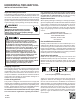
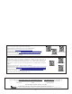
Cased Coil
3" MIN.
POSITIVE LIQUID SEAL
REQUIRED AT TRAP
Drain
Connection
2" MIN.
Figure 4
Condensate Drain Trap
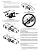
The depth of a running trap (Figure 5) should be either 1" or a
depth that permits unrestricted condensate drainage without
excessive air discharge.
Field experience has shown condensate drain traps with an
open vertical Tee between the air handler and the condensate
drain trap can improve condensate drainage in some applica-
tions, but may cause excessive air discharge out of the open
Tee. The manufacturer does not prohibit this type of drain but
we also do not recommend it due to the resulting air leakage.
Regardless of the condensate drain design used, it is the
installer’s responsibility to ensure the condensate drain sys-
tem is of sufficient design to ensure proper condensate re-
moval from the coil drain pan.
PITCH
TOWARDS
DRAIN
1” MIN
TRAP
CONDENSATE
DRAIN CONN.
CONNECT DRAIN
SAME SIZE AS ON
UNIT OR LARGER
Figure 5
Running Trap
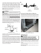
Horizontal Coil Water Blower-Off Bracket
CHPF4860 coils are shipped with an accessory kit containing
a sheet metal bracket. For horizontal-left applications where
the airflow may exceed 1600 CFM, this bracket must be
installed on the left side of the drain pan as shown in Figure 6.
Figure 6
Horizontal Blow-Off Bracket
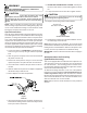
Refrigerant Lines
A quenching cloth is strongly recommended to
prevent scorching or marring of the equipment
finish when welding close to the painted surfaces.
Use brazing alloy of 5% minimum silver content.
WARNING
All cut ends are to be round, burr free, and cleaned. Any other
condition increases the chance of a refrigerant leak. Use a
pipe cutter to remove the closed end of the spun closed suc-
tion line.
To avoid overheating after brazing, quench all welded joints
with water or a wet rag.
For the correct tubing size, follow the specification for the con-
denser/heat pump