
CAPF R-22 Service Manual


SERVICING
59
S-107 UNDERFEEDING
Underfeeding by the expansion valve results in low system
capacity and low suction pressures.
If these symptoms are observed:
1. Check for a restricted liquid line or drier. A restriction will
be indicated by a temperature drop across the drier.
2. Check the operation of the power element of the valve as
described in S-110 Checking Expansion Valve Operation.
S-108 SUPERHEAT
The expansion valves are factory adjusted to maintain 12 to
18 degrees superheat of the suction gas. Before checking
the superheat or replacing the valve, perform all the proce-
dures outlined under Air Flow, Refrigerant Charge, Expan-
sion Valve - Overfeeding, Underfeeding. These are the most
common causes for evaporator malfunction.
CHECKING SUPERHEAT
Refrigerant gas is considered superheated when its tempera-
ture is higher than the saturation temperature corresponding
to its pressure. The degree of superheat equals the degrees
of temperature increase above the saturation temperature at
existing pressure. See Temperature - Pressure Chart on
following pages.
1. Run system at least 10 minutes to allow pressure to
stabilize.
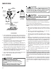
2. Temporarily install thermometer on suction (large) line near
suction line service valve with adequate contact and insulate
for best possible reading.
3. Refer to the superheat table provided for proper system
superheat. Add charge to lower superheat or recover charge
to raise superheat.
Superheat Formula = Suct. Line Temp. - Sat. Suct. Temp.
EXAMPLE:
a. Suction Pressure = 98.7
b. Corresponding Temp. °F. = 50
c. Thermometer on Suction Line = 61°F.
To obtain the degrees temperature of superheat, subtract
50.0 from 61.0°F.
The difference is 11° Superheat. The 11° Superheat would fall
in the ± range of allowable superheat.
NOTE: If superheat is measured for long line set or attic
application, there may be a significant difference in the
superheat from evaporator out to suction valve.
SUPERHEAT AND SUBCOOLING ADJUSTMENT ON TXV
APPLICATIONS
1. Run system at least 10 minutes to allow pressure to
stabilize.
2. Temporarily install thermometer on liquid (small) line near
liquid line service valve with adequate contact and insu-
late for best possible reading.
3. Check subcooling and superheat. Systems with TXV
application should have a subcooling and superheat of 7
± 2ºF.
a. If subcooling and superheat are low, adjust TXV to 7 -
9ºF then check subcooling.
b. If subcooling is low and superheat is high, add charge
to raise subcooling to 7 ± 2ºF then check superheat.
c. If subcooling and superheat are high, adjust TXV valve
to 7 ± 9ºF then check subcooling.
d. If subcooling is high and superheat is low, adjust TXV
valve to 7 to 9ºF superheat and remove charge to lower
the subcooling to 7 ± 2ºF.
The TXV should NOT be adjusted at light load conditions 55º
to 60ºF, under such conditions only the subcooling can be
evaluated. This is because suction pressure is dependent on
the indoor coil match, indoor airflow, and wet bulb tempera-
ture. NOTE: Do NOT adjust charge based on suction pres-
sure unless there is a gross undercharge.
4. Disconnect manifold set. Installation is complete.