
ComfortNet Control System Installation Guide


CTK04 ComfortNet™ Communicating Thermostat
3
I/O-CHTSTAT03 69-2688—07
Installation
Thisbookletcontainsinstallationinstructionsandinformationonthethermostatand
wirelessaccessories.Separateinstallationinstructionsforthefurnaceorairhandler
andoutdoorACcondensingunitorheatpumpareprovidedwiththeappropriate
equipment.ThisthermostatisdesignedexclusivelyforusewiththeComfortNetcom-
municating system.
Valid System Configurations
Thiscontrolmayonlybeusedwithcertainsystemconfigurations.Validsystemcon-
figurationsforwhichthiscontrolcanbeusedare:
• AcommunicatingairhandlermatchedwithacommunicatingoutdoorAC
condensing unit.
• Acommunicatingairhandlermatchedwithacommunicatingoutdoorheatpump
unit.
• AcommunicatingfurnacematchedwithacommunicatingoutdoorACcondensing
unit.
• Acommunicatingfurnacematchedwithacommunicatingoutdoorheatpumpunit.
• Acommunicatingfurnacematchedwithanon-communicatingsinglestageAC
condensing unit.
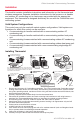
Installing Thermostat
1. RemoveandinventoryallComfortNetcomponents.TheCTK04containstheComfortNetcommu-
nicatingthermostat,lithiumcoincellbattery,wallmountingscrewsandanchors,systeminstalla-
tionguide,operatingmanual,transformerandawiringsetthatincludestwoterminalblocks,two
sheetmetalscrewsandwires.
2. Carefullyseparatethethermostatbodyfromthethermostatbase.
3. Placebaseatinstallationlocationandmarkmountingholelocationsonwallusingbaseasa
template.SeeThermostatMountingsectiononnextpageforoptimalmountinglocation.
4. Drillmountingholes.Drill3/16"holesfordrywalland7/32"holesforplaster.
5. Attachbasefirmlytowallusingtwomountingscrews.Levelingisforappearanceonlyandwill
not affect thermostat operation.
6. Connectwirestoterminalblockonbase.
7. 18AWGsolidwireisrecommended.
8. Pushexcesswireintowallandplugholewithafireresistantmaterial(suchasfiberglassinsula-
tion)topreventdraftsfromaffectingthermostatoperation.
9. Insertcoincellbatteryinthebackofthethermostat.
10. Carefullylineupthethermostatwiththebaseandsnapintoplace.
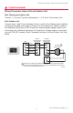
HIGH
VOLTAGE
TRANSFORMER LOW
VOLTAGE CONNECTED
TO R AND C
TERMINALS
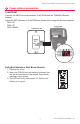
CONNECT 2-WIRES TO
INDOOR UNIT
REMOVE AND INVENTORY ALL
COMFORTNET
™
COMPONENTS
REMOVE OUTDOOR UNIT
COVER AND 7-PIN
CONNECTOR
NOTE: THE CTK04 CONTAINS THE THERMOSTAT, LITHIUM COIN CELL BATTERY,
WALL MOUNTING SCREWS AND ANCHORS, SYSTEM INSTALLATION GUIDE,
OPERATING MANUAL, TRANSFORMER AND A WIRING SET THAT INCLUDES
TWO TERMINAL BLOCKS AND WIRES.
P/N F0430675005
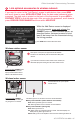
INSTALL HVAC COMPONENTS
GAS
FURNACE
AIR
HANDLER
TERMINALS 1 & 2 ARE
COMMUNICATIONS
WIRES. THEY SHOULD
NEVER BE CONNECTED
TO THE 24 VAC R&C
POWER SUPPLY
TERMINALS.
CONNECT 4-WIRES
FROM STAT AND
2 WIRES FROM
OUTDOOR UNIT
P/N F0430679005
P/N F0430673005
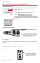
CONNECT TO THE OUTDOOR UNIT
2-WIRE/TRANSFORMER
CONNECTION
CONNECT HIGH VOLTAGE TRANSFORMER LEADS TO L1
AND L2 MALE SPADE TERMINALS ON CIRCUIT BOARD.
DO NOT CONNECT R AND C BETWEEN THE INDOOR UNIT
AND OUTDOOR UNIT. SEE PAGE 5.
INSTALL THERMOSTAT ON INTERIOR WALL
NOTE: THERMOSTAT WILL
AUTOMATICALLY CONFIGURE
TO THE SYSTEM ONCE HIGH
VOLTAGE POWER IS
APPLIED TO THE
INDOOR AND
OUTDOOR
EQUIPMENT.
M33487B
1
REMOVE 9-PIN CONNECTOR
FROM FURNACE OR AIR
HANDLER CONTROL
2
3
4
5
6
AIR CONDITIONER
OR HEAT PUMP
AIR CONDITIONER
OR HEAT PUMP
TRANSFORMER
ADDITIONAL TRANSFORMER
IS NOT REQUIRED FOR
INVERTER/VARIABLE SPEED
OUTDOOR COMMUNICATING
UNITS.
ADDITIONAL TRANSFORMER
IS REQUIRED FOR 2-STAGE
OUTDOOR COMMUNICATING
UNITS.
LOW (24 VAC)
VOLTAGE