
AVPTC Service Manual
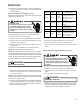
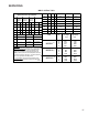
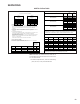

BLOWER PERFORMANCE DATA
68
1234 5 6
400 600 OFF
OFF
OFF
OFF
OFF
OFF
540 800 ON
OFF
ON
OFF
ON
OFF
670 1000 OFF
ON
OFF
ON
OFF
ON
800 1200 ON
ON
ON
ON
ON
ON
670 1000 OFF
OFF
OFF
OFF
OFF
OFF
800 1200 ON
OFF
ON
OFF
ON
OFF
940 1400 OFF
ON
OFF
ON
OFF
ON
1070 1600 ON
ON
ON
ON
ON
ON
800 1200 OFF
OFF
OFF
OFF
OFF
OFF
1070 1600 ON
OFF
ON
OFF
ON
OFF
1200 1800 OFF
ON
OFF
ON
OFF
ON
1340 2000 ON
ON
ON
ON
ON
ON
^ Factory setting
ADJUST SELECTION
SWITCHES
PROFILE SELECTION
SWITCHES
MBVC1200
MBVC1600
MBVC2000
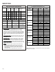
COOL SELECTION
SWITCHES
MODEL
LOW STAGE
COOL
HIGH STAGE
COOL
HTR kW MBVC1200* MBVC1600* MBVC2000*
SWITCH
9
SWITCH
10
SWITCH
11
3 600 800 800
ON ON ON
5 600 800 800
ON ON OFF
6 635 800 800
ON OFF ON
8 740 1000 1000
ON OFF OFF
10 1000 1000 1200
OFF ON ON
15 1400 1500 1500
OFF ON OFF
20 NR NR 2000
OFF OFF ON
21
NR NR NR ON^ ON^ ON^
^ Factory setting
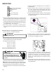
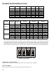
Locate the blower speed selection DIP switches on the integrated control module. Select the desired “cooling”
speed tap by positioning switches 1 and 2 appropriately. Select the desired "adjust" tap by positioning switches
3 and 4 appropriatly. Refer to the following Dipswitches - Cooling Airflow and Airflow Adjust Taps figure for switch
positions and their corresponding taps. Verify CFM by counting the number of times the green CFM LED blinks.
3
4
OFF OFF OFF OFFON ON ON ON
Normal*
+10%
Air flow Adjust Taps (*indicates factory setting)
-10% Normal
3
4
3
4
3
4
Dip Switches - Cooling Airflow and
Airflow Adjust Taps
Thermostat "Fan Only" Mode
During"Fan Only" operations, the CFM output is 30% of the maximum CFM capability.
CFM Trim Adjust
Minor adjustments can be made through the dipswitch combination of 3-4.