
AVPTC Service Manual

SERVICING
36
Diagnostics
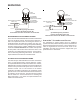
Accessing the air handler’s diagnostics menu provides ready
access to the last six faults detected by the air handler.
Faults are stored most recent to least recent. Any consecu-
tively repeated fault is stored a maximum of three times.
Example: A clogged return air filter causes the air handler’s
motor to repeatedly enter a limiting condition. The control will
only store this fault the first three consecutive times the fault
occurs.
NOTE: It is highly recommended that the fault history be
cleared after performing maintenance or servicing the air
handler.
Network Troubleshooting
The ComfortNet™ system is a fully communicating system,
and thus, constitutes a network. Occasionally the need to
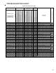
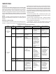
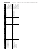
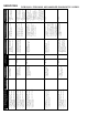
COMMUNICATIONS T ROUBLESHOOTING C HART
LED LED
Status
Indication Possible Causes Corrective Action(s) Notes & Cautions
Off
x Normal condition x None x None x None
1 Flash
x Communications
Failure
x Communications
Failure
x Depress Learn Button
x Verify that bus BIAS
and TERM
dipswitches are in the
ON position.
x Depress once
quickly for a power-
up reset
x Depress and hold
for 2 seconds for
an out-of-box reset
Red
Communications
LED
2 Flashes
x Out-of-box reset x Control power up
x Learn button
depressed
x None x None
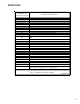
Off
x No power
x Communications
error
x No power to air
handler
x Open fuse
x Communications error
x Check fuses and
circuit breakers;
replace/reset
x Replace blown fuse
x Check for shorts in
low voltage wiring in
air handler/system
x Reset network by
depressing learn
button
x Check data 1/ data 2
voltages
x Turn power OFF
prior to repair
1 Steady
Flash
x No network found x Broken/ disconnected
data wire(s)
x Air handler is installed
as a non-
communicating/
traditional system
x Check
communications
wiring (data 1/ data 2
wires)
x Check wire
connections at
terminal block
x Verify air handler
installation type (non-
communicating/
traditional or
communicating)
x Check data 1/ data 2
voltages
x Turn power OFF
prior to repair
x Verify wires at
terminal blocks are
securely twisted
together prior to
inserting into
terminal block
x Verify data1 and
data voltages as
described above
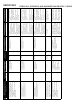
Rapid
Flashing
x Normal network
traffic
x Control is “talking” on
network as expected
x None x None
Green Receive
LED
On Solid
x Data 1/ Data 2
miss-wire
x Data 1 and data 2
wires reversed at air
handler, thermostat,
or ComfortNet™
compatible outdoor
AC/HP
x Short between data 1
and data 2 wires
x Short between data 1
or data 2 wires and R
(24VAC) or C (24VAC
common)
x Check
communications
wiring (data 1/ data 2
wires)
x Check wire
connections at
terminal block
x Check data 1/ data 2
voltages
x Turn power OFF
prior to repair
x Verify wires at
terminal blocks are
securely twisted
together prior to
inserting into
terminal block
x Verify data1 and
data voltages as
described above
troubleshoot the network may arise. The integrated air han-
dler control has some on-board tools that may be used to
troubleshoot the network. These tools are: red communica-
tions LED, green receive (Rx) LED, and learn button. Refer to
the Communications Troubleshooting Chart and Air Handler
Diagnostic Codes below for error codes, possible causes and
corrective actionS.
• Red communications LED – Indicates the status of the
network. The table below indicates the LED status and the
corresponding potential problem.
• Green receive communication LED – Indicates network
traffic. The table below indicates the LED status and the
corresponding potential problem.
• Learn button – Used to reset the network. Depress the
button for approximately 2 seconds to reset the network.