
AVPTC Installation Instructions ComfortBridge

4
6.1 UpowInstallaon
No eld modicaons are mandatory; however, to obtain
maximum eciency, the horizontal drip shield, side drain pan
and drain pan extension can be removed.
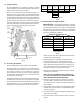
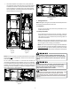
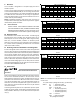
Side Drain Pan and Extension Removal: Refer to Figure 1, re-
move the two (2) screws that secure the drip shield support
brackets to the condensate collectors (front and back). Unsnap
the side drain pan from the main drain pan using a screw driver
or any small lever. The side drain pan, drip shield brackets and
the drain pan extension may now be removed. From Figure 1,
drain port labeled (A) is the primary drain for this applicaon
and condensate drain line must be aached to this drain port.
Drain port (a) is for the secondary drain line (if used).
Drip Pan
Extension
Side
Drain
Pan
Screw
B
b
A
Main Drain Pan
Drip Shield Bracket
Drip Shield
Pna
SIDE DRAIN PAN REMOVAL
Figure 1
6.2 HorizontalLeInstallaon
No eld modicaons are permissible for this applicaon.
The boom right drain connecon is the primary drain for
this applicaon and condensate drain line must be aached
to this drain connecon. The top connecon of the three
drain connecons on the drain pan must remain plugged for
this applicaon. The boom le drain connecon is for the
secondary drain line (if used).
In applicaons where the air handler is installed in the horizon-
tal le posion, and the return air environment see humidity
levels above 65% relave humidity coupled with total external
stac levels above 0.5” e.s.p., a condensate kit is available for
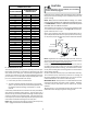
eld applicaon. Kit nomenclature can be found in Table 1.
CMK000 8
Condensate
Kit
CMK000 9
Condensa te
Kit
CMK001 0
Condensate
Kit
CMK0012
Condensa te
Kit
CMK001 3
Condensate
Kit
CMK001 4
Condensa te
Kit
AVPTC25B14 AVPTC29B14 AVPTC31C14 AVPTC49D14 AVPTC33C14 AVPTC49C14
AVPTC37B14 AVPTC37C14 AVPTC61D14 AVPTC39C14
AVPTC37D14
AVPTC59C14
AVPTC59D14
CONDENSATE KIT
TABLE 1
6.3 Downow/HorizontalRightInstallaon
IMPORTANT NOTE: In the downow applicaon, to prevent
coil pan “sweang”, a downow kit (DFK) is available through
your local Goodman distributor. The DFK is not supplied with
the air handler and is required by Goodman on all downow
installaons. See Table 2 for the correct DFK and follow the
instrucons provided for installaon.
DFK-B DFK-C DFK-D
AVPTC25B14** AVPTC31C14** AVPTC37D14**
AVPTC29B14** AVPTC37C14** AVPTC49D14**
AVPTC35B14** AVPTC59C14** AVPTC59D14**
AVPTC37B14** AVPTC33C14** AVPTC61D14**
AVPTC39C14**
AVPTC49C14**
MODEL LIST FOR DOWNFLOW KITS
DOWNFLOW KIT
TABLE 2
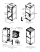
Refer to Figure 6 and 7 for the locaon of the components
referenced in the following steps.
1. Before inverng the air handler, remove blower access
panel and coil access panel. The coil access panel and
tubing panel may remain screwed together during this pro-
cedure. Remove and retain the seven (7) screws securing
the coil access panel to the cabinet and the six (6) screws
securing the blower access panel to the cabinet.
2. Slide the coil assembly out using the drain pan to pull the
assembly from the cabinet.
NOTE: DO NOT USE MANIFOLDS OR FLOWRATOR TO
PULL THE COIL ASSEMBLY OUT. FAILURE TO DO SO MAY
RESULT IN BRAZE JOINT DAMAGE AND LEAKS.
3. Removal of the center support is required on units with
21” wide cabinet. Remove and retain the two (2) screws
that secure the center support to the cabinet. Remove the
center support.
4. Using the drain pan to hold the coil assembly, slide the coil
assembly back into the cabinet on the downow brackets
as shown in Figure 8.
5. Re-install the center support (if removed) using the two (2)
screws removed in Step 4.
6. Re-install the access panels removed in Step 1 as shown in
Figure 9.