
AVPTC Installation Instructions ComfortBridge

12
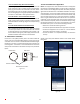
This air handler is Bluetooth ready and funcons with the Cool
Cloud HVAC phone applicaon designed to improve the contrac-
tor’s setup / diagnosc experience. Users can see specic model
informaon, review acve diagnosc error codes, observe system
menu tesng of all operaonal modes (heat / cool / fan) directly
from the phone. The phone applicaon is also capable of directly
updang the air handler soware anyme updates are available.
The applicaon will automacally nofy the user.
NOTE: The soware update may take up to 20 minutes to complete.
16 QuickStartGuideforCommunicangOutdoorUnits
EXTREMELY IMPORTANT: For all cooling calls the system only re-
quires a single Y input from the thermostat. For all heang calls
(including applicaons with backup electric heater kits) the system
only requires a single W input from the thermostat. Internal algo-
rithms will control all available cooling and heang stages based
on these inputs. Any single-stage 24VAC thermostat can be used.
For proper operaon, the thermostat must be setup to control a
single stage AC outdoor unit and to control single stage electric
heat operaon. The control board does not accommodate an O
wire thermostat input (reversing valve signal). If a heat pump is
installed, the thermostat should be setup as stated above. Seng
the thermostat for the heat pump control or mulstage control
may result in incorrect performance.
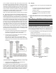
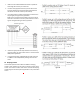
1. Connect all necessary thermostat wires to the thermostat
connector on the air handler control as instructed by the
applicable wiring diagrams shown in this secon.
2. Connect the 1 & 2 wires between the indoor and outdoor
unit for communicang operaon.
Note: Verify two stage outdoor units include a 24VAC
transformer (for outdoor control board power). Two stage
outdoor units may not behave properly without this 24 VAC
transformer.
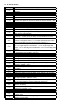
Figure 15
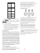
3. Download the Cool Cloud HVAC phone applicaon for
charging and to congure /test system.
NOTE: When new versions of Bluetooth Communicaon Soware
and Air Handler Control Soware are available, the phone appli-
caon noes the user. Soware updates are classied as either
oponal or mandatory and installed by using the phone applicaon.
Ensure all mandatory soware updates and install if necessary.
16.1 Charging
1. Two-stage outdoor units using the Cool Cloud HVAC appli-
caon:
a. Using the cooling icon aer entering the outdoor
unit menus, energize the outdoor unit at 49%
capacity or lower.
b. Charge the outdoor unit as required using the
charging informaon provided with the outdoor
equipment.
17 QuickStartGuideforNon-CommunicangOutdoor
Units
Whenseng up a ComfortBridgeair handler foruse with a
Non-Communicangoutdoorunityou mustset airow in the
“ton” menu on the PCB or in the CoolCLoud HVAC APP. Failure
to do so will result in the air handler PCB displaying “IdL” and the
blowerwillnotoperatewithacallforcooling.TheBoarddoes
notneedtobereplaced,youMUSTsettheairowrst.
EXTREMELY IMPORTANT: For two stage electric heat kit control
the system only needs a single W input. Internal algorithms will
control staging automacally based on the single W input. For
non-communicang outdoor unit wiring, see instrucons below:
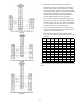
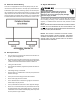
1. Use the wiring diagrams on the next page to connect low
voltage thermostat wires.
NOTE: When installing the air handler with a non-com-
municang heat pump, wire directly to the “O” terminal
on the non-communicang heat pump. See the following
gures.
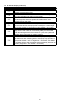
Figure 16