
Condensing Unit, Heat Pump, Blower and Coil Service Instructions

SERVICING
78
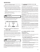
Figure 1
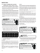
Figure 2
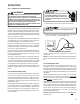
Reconnect communicating wires from outdoor
board check voltage again
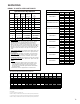
1. Check voltage from C to data 1 and C to Data 2 if the
voltage is different than the original reading listed
above. The outdoor bias switches must be turned to
off.
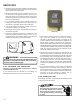
2. Turn power off at outdoor unit and unplug the low
voltage connector.
3. Remove the plastic film covering the switches with
screwdriver or knife.
4. Turn both switches to “off” position.
5. Plug in connector and turn on power and check DC
voltage between C and data 1 and C and data 2.
Difference should be .6vdc.
SEQUENCE OF OPERATION
AVPTC/MBVC with ASXC/DSXC Condenser and CTK0*
Communicating Themostat
The AVPTC or MBVC air handle/modular blower matched
with an ASXC or DSXC condensing unit and CTK0* commu-
nicating thermostat constitute a network. The three compo-
nents, or subsystems, making up the system communicate
with one another with information passed between all three
components. This leads to a somewhat non-traditional
manner in which the system components receive commands
for system operation. All system commands are routed from
the component through the network to the appropriate desti-
nation component.
NOTE: The individual subsystems will cease operation if the
request for operation is NOT refreshed after 5 minutes. This
is a built-in safe guard to prevent the possibility of runaway
operation.
1.0 Cooling Operation - Low and High Stage Cool
1.1 The CTK0* thermostat sends a request for low stage
cooling through the network to the unitary (UC) control in
the condenser. The UC control receives the command
and processes any compressor and fan delays.
1.2 The UC control sends a request for low stage fan speed
to the air handler/modular blower. The blower energizes
the ECM blower motor at the appropriate speed.
1.3 The condenser energizes the compressor and con-
denser fan motor at the appropriate low stage speeds.
1.4 The system operates at low stage cooling.
1.5 If the thermostat demand cannot be met on low stage
cooling, the CTK0* thermostat sends a request for high
stage cooling to the condenser. The condenser in turn
sends a request for high stage fan speed to the air
handler/modular blower. The blower increases the blower
speed to the high stage cooling speed.
1.6 The condenser's unitary control energizes the high stage
compressor solenoid and switches the condenser fan
motor to high speed.
1.7 The system operates at high stage cooling.
1.8 Once the thermostat demand is satisfied, the CTK0*
thermostat commands the UC control to end cooling
operation. The condenser de-energizes the
compressorand condenser fan motor. The UC control
continues providing a fan request until any cooling blower
OFF delays have expired.
2.0 Heating Operation - Auxiliary/Emergency Heat
2.1 The CTK0* thermostat sends a request for emergency
heat to the air handler/modular blower.
2.2 The air handler control energizes the ECM blower motor
at the emergency heat speed. The electric heat se-
quencer outputs are also energized, thus energizing the
electric heaters.
2.3 The system operates at emergency heat.
2.4 Once the thermostat demand is satisfied, the CTK0*
thermostat commands the air handler/modular blower to
end emergency heat operation. The air handler control
de-energizes the electric heat sequencer outputs. The
ECM blower motor remains energized until any blower
OFF delay timing has expired.
3.0 Continuous Fan Operation
3.1 With a demand for continuous fan operation, the CTK0*
thermostat sends a fan request to the integrated air