
Condensing Unit, Heat Pump, Blower and Coil Service Instructions

SERVICING
77
1. Turn on power to air handler or modular blower.
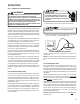
WARNING
Line Voltage now present.
2. Disconnect the 4-circuit harness connecting the control
to the electric heater kit.
3. Provide a thermostat demand for low stage auxiliary heat
(W1). Measure the voltage between circuits 1 and 3 at
the on-board electric heat connector. Voltage should
measure 24VAC. Replace control if no voltage is present.
NOTE: Allow for any built-in time delays before making
voltage measurements. Any electric heater faults that are
present may prevent the heater output from energizing.
Verify that no heater faults are present before making
voltage measurements.
4. Provide a thermostat demand for high stage auxiliary heat
(W1 + W2). Measure the voltage between circuits 1 and
3 at the on-board electric heat connector. Measure the
voltage between circuits 2 and 3 at the on-board electric
heat connector. Voltage should measure 24VAC. Re-
place control if no voltage is present.
Communications (Applies only to Systems with Compatible
ComfortNet
TM
Outdoor Unit and CTK0*Thermostat)
The integrated air handler control has some on-board tools
that may be used to troubleshoot the network. These tools
are: red communications LED, green receive (Rx) LED, and
learn button. These are described below
a. Red communications LED – Indicates the status of the
network. Refer to the Network Troubleshooting Chart for
the LED status and the corresponding potential problem.
b. Green receive LED – Indicates network traffic. Refer to
the Network Troubleshooting Chart for the LED status
and the corresponding potential problem.
c. Learn button – Used to reset the network. Depress the
button for approximately 2 seconds to reset the network.
Voltages between the two data lines and between each data
line and common may be used to determine if the network
is operating properly.
Do the following to measure the voltages on the communi-
cations data lines.
WARNING
Line Voltage now present.
Data Line Voltage Troubleshooting and Bias
Switches
Proper data voltage is essential to robust and reliable
communication on the ComfortNet™ system. Any wiring
issues must be corrected for good communication.
• Poor wiring connections at the terminal blocks
• Low voltage wires that are shorted, grounded or
broken.
• Communicating wires that are not connected to the
proper terminals at the connector.
• 24 volt common outside and inside are not at the
same ground potential
• Bias dip switch setting conflicts between indoor
board and outdoor board.
• It is STRONGLY recommended that you do not
connect multiple wires into a single terminal on the
wiring connector
• Wire nuts are recommended to connect multiple
wires to connector ensuring one wire is used for each
terminal.
• Failure to do so may result in intermittent operation.
• Typical 18 AWG thermostat wire may be used to wire
the system components. One hundred feet is the
maximum length of wire between indoor and outdoor
units or between indoor unit and thermostat.
• When outdoor transformer is used and there at least
three thermostat wires running to the outdoor unit
use one of the extra wires to connect the two 24 volt
commons together. This will ensure both 24 volt
commons are at the same ground potential.
• When outdoor transformer is used and there are only
two thermostat wires running to the outdoor unit
ground the 24 volt common “C” of the outdoor
transformer to a chassis ground (earth0 ground. This
is not as good as the third wire but it is better than
leaving the outdoor 24 volt common floating.
If this does not resolve communication issues Bias switch
issues will need to be checked.
Note: Only one unit should control bias on the system.
• Air Handler or Furnace should never have their bias
switches moved.
• Indoor bias switches are always in the “ON” position
• A/C and Heat Pump bias switches can be moved.
• Thermostats do not have bias switches.
• It may be necessary to move bias switches on the
outdoor unit to achieve proper bias. If the switches
need to be moved both switches must be moved.
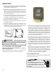
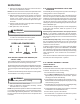
Checking Bias Voltage:
Remove communicating wires from outdoor board and
thermostat and check voltage at the indoor board.
1. DC voltage from C to data 1 should read approxi-
mately 1.9vdc or 2.8vdc for some furnaces. (Figure 1)
2. DC voltage from C to data 2 should read approxi-
mately 1.3vdc. or 2.2vdc for some furnaces . (Figure
2)
3. Difference in voltage should be .6vdc.