
AVPTC14 oddnum Installation Instructions

20
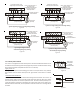
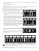
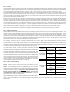
20.3 CTK03/04 Four-Wire Indoor, Three-Wire Outdoor Wiring
Three wires should be utilized between the indoor and outdoor units. For this wiring scheme, two wires for the data lines, 1 and 2 are
required and a wire connecting the common “C” terminals between the indoor and outdoor units. This connects both commons to the
same ground potential allowing for better communication. A 40VA, 208/230 VAC to 24 VAC transformer must be installed in the
outdoor unit to provide 24 VAC power to the outdoor unit’s elec-
tronic control. The transformer is included with the CTK0* kit.
See kit instructions for mounting and wiring instructions. Four
wires are required between the indoor unit and thermostat.
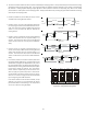
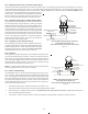
20.4 CTK03/04 Four-Wire Indoor, Two-Wire Outdoor Wiring
Two wires may be utilized between the indoor and outdoor units.
For this wiring scheme, only the data lines, 1 and 2, are required
between the indoor and outdoor units. A 40VA, 208/230 VAC to
24 VAC transformer must be installed in the outdoor unit to pro-
vide 24 VAC power to the outdoor unit’s electronic control. The
“C” 24v common of the outdoor transformer should be grounded
to the equipment (earth) ground. Not as secure as the third wire
but it insures there is not a floating “C” 24v common. The trans-
former is included with the CTK0* kit. See kit instructions for
mounting and wiring instructions. Four wires are required be-
tween the indoor unit and thermostat.
20.5 ComfortNet™ System Advanced Features
The ComfortNet system permits access to additional system in-
formation, advanced set-up features, and advanced diagnostic/
troubleshooting features. These advanced features are orga-
nized into a menu structure. See the AIR HANDLER ADVANCED
FEATURES MENU section for layout of menu shortcuts.
20.6 Diagnostics
Accessing the air handler’s diagnostics menu provides ready access to the
last six faults detected by the air handler. Faults are stored most recent to
least recent. Any consecutively repeated fault is stored a maximum of three
times. Example: A clogged return air filter causes the air handler’s motor to
repeatedly entera limiting condition. The control will only store this fault
the first three consecutive times the fault occurs.
NOTE: It is highly recommended that the fault history be cleared after
performing maintenance or servicing the air handler.
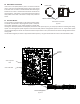
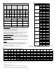
20.7 Network Troubleshooting
The ComfortNet system is a fully communicating system, and thus, consti-
tutes a network. Occasionally the need to troubleshoot the network may
arise. The integrated air handler control has some on-board tools that may
be used to troubleshoot the network. These tools are: red communications
LED, green receive (Rx) LED, and learn button. Refer to the Communica-
tions Troubleshooting Chart at the end of this manual for error codes, pos-
sible causes and corrective actions.
• Red communications LED – Indicates the status of the network. The
table below indicates the LED status and the corresponding potential problem.
• Green receive LED – Indicates network traffic. The
COMMUNICATIONS TROUBLESHOOTING CHART indicates the LED status and
the corresponding potential problem.
• Learn button – Used to reset the network. Depress the button for approximately 2 seconds to reset the network.
1
2R
C
12RC
12
RC
CTK0*
Thermostat
CT Compatible
Modular Blower
Integrated Control Module
CT Compatible
AC/HP Integrated
Control Module
40VA Transformer (included in
CTK0*** kit)
208/230 VAC
24 VAC
CTK03 & CTK04 System Wiring Using Three-Wires
between Air Handler and AC / HP
and Four Wires between Air Handler and Thermostat
Figure 33
1
2R
C
12RC
12
RC
CTK0*
Thermostat
CT Compatible
Modular Blower
Integrated Control Module
CT Compatible
AC/HP Integrated
Control Module
40VA Transformer (included in
CTK0*** kit)
208/230 VAC
24 VAC
CTK03 & CTK04 System Wiring Using Two-Wires
between Air Handler and AC / HP
and Four Wires between Air Handler and Thermostat
Figure 34