
AVPTC Installation Instructions ComfortBridge

9
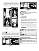
9 Ductwork
This air handler is designed for a complete supply and return
ductwork system.
To ensure correct system performance, the ductwork is to be sized
to accommodate 350-450 CFM per ton of cooling with the stac
pressure not to exceed 0.5” in w.c. Refer to ACCA Manual D, Manual
S and Manual RS for informaon on duct sizing and applicaon.
Flame retardant ductwork is to be used and sealed to the unit in a
manner that will prevent leakage.
NOTE: A downow applicaon with electric heat must have an
L-shaped sheet metal supply duct without any outlets or registers
located directly below the heater.
9.1 ReturnDuctwork
DO NOT LOCATE THE RETURN DUCTWORK IN AN AREA
THAT CAN INTRODUCE TOXIC, OR OBJECTIONABLE FUMES/
ODORS INTO THE DUCTWORK. The return ductwork is to be
connected to the air handler boom (upow conguraon).
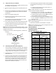
10 Return Air Filters
Each installaon must include a return air lter. This ltering may
be performed at the air handler using the factory lter rails or
externally such as a return air lter grille. When using the factory
lter rails, a nominal 16x20x1”, 20x20x1” or 24x20x1” (actual
dimension must be less than 23-½”x20”) lter can be installed on
a B, C and D cabinet respecvely (the cabinet size is the seventh
leer of the model number).
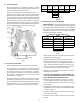
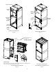
11 Achieving1.4%and2.0%AirowLowLeakageRate
Ensure all the gaskets remain intact on all surfaces as shipped with
the unit. These surfaces are areas between the upper e plate and
coil access panel, blower access and coil access panels, and between
the coil access and lter access panels. Ensure upon installaon,
that the plasc breaker cover is sing ush on the blower access
panel and all access panels are ush with each other and the
cabinet. With these requirements sased, the unit achieves less
than 1.4% airow leakage @ 0.5 inch wc stac pressure and less
than 2% airow leakage @1inch wc stac pressure when tested in
accordance with ASHRAE Standard 193.
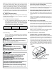
12 Electric Heat
Do not operate this product without all the ductwork
attached.
Refer to the installaon manual provided with the electric heat kit
for the correct installaon procedure. All electric heat must be
eld installed. If installing this opon, the ONLY heat kits that are
permied to be used are the HKS series. Refer to the air handler
unit’s Serial and Rang plate or the HKS specicaon sheets to
determine the heat kits compable with a given air handler. No
other accessory heat kit besides the HKS series may be installed
in these air handlers.
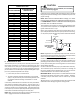
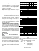
The heang mode temperature rise is dependent upon the system
airow, the supply voltage, and the heat kit size (kW) selected. Use
data provided in Tables 3, 4 and 5 to determine the temperature
rise (°F).
3 5 6 8 1 0 1 5 19/2 0 2 5
8 0 0 1 2 1 9 2 3 3 1 3 7 5 6
1 0 0 0 9 1 5 1 9 2 5 3 0 4 4
1 2 0 0 8 1 2 1 5 2 1 2 5 3 7 4 9 6 2
1 4 0 0 7 1 1 1 3 1 8 2 1 3 2 4 2 5 3
1 6 0 0 6 9 1 2 1 5 1 9 2 8 3 7 4 6
1 8 0 0 5 8 1 0 1 4 1 6 2 5 3 3 4 1
2 0 0 0 5 7 9 1 2 1 5 2 2 3 0 3 7
C FM
H EA T K IT N O M IN A L k W
230/1/60 SUPPLY VOLTAGE - TEMP. RISE °F
Table 3
3568 1 0 1 5 1 9 /2 0 2 5
8 0 0 1 1 1 8 2 2 3 0 3 5 5 4
1 0 0 0 9 1 4 1 8 2 4 2 8 4 2
1 2 0 0 7 1 2 1 5 2 0 2 4 3 5 4 7 5 9
1 4 0 0 6 1 0 1 3 1 7 2 0 3 0 4 0 5 1
1 6 0 0 6 9 1 1 1 5 1 8 2 7 3 5 4 4
1 8 0 0 5 8 1 0 1 3 1 6 2 4 3 1 3 9
2 0 0 0 479 1 2 1 4 2 1 2 8 3 5
C FM
H EAT K IT NO M IN A L k W
220/1/60 SUPPLY VOLTAGE - TEMP. RISE °F
Table 4
3568 1 0 1 5 1 9 /2 0 2 5
8 0 0 10 17 2 1 2 8 3 3
1 000 8 13 1 7 2 2 2 7 4 0
1 200 7 11 1 4 1 9 2 2 3 3 4 5 5 6
1 400 6 10 1 2 1 6 1 9 2 9 3 8 4 8
1 600 5 8 1 0 1 4 1 7 2 5 3 3 4 2
1 800 579 12 1 5 2 2 3 0 3 7
2 000 478 11 1 3 2 0 2 7 3 3
CFM
HEAT KIT NO M INAL k W
208/1/60 SUPPLY VOLTAGE - TEMP. RISE °F
Table 5
3568 10 15 19 20 25
AVPTC25B14 550 650 700 800 850 875
AVPTC29B14 550 650 700 800 875 875
AVPTC35B14 550 650 700 800 875 1050
AVPTC37B14 550 650 700 800 875 1050
AVPTC31C14 600 700 770 880 970 1090 1280
AVPTC33C14 600 700 750 850 920 950
AVPTC37C14 700 770 880 970 1090 1280
AVPTC39C14 700 770 880 970 1090 1280
AVPTC49C14 800 800 950 1090 1290 1345
AVPTC59C14 800 800 950 1090 1290 1345
AVPTC37D14 870 970 1060 1120 1220 1250
AVPTC49D14 950 1060 1150 1220 1520
AVPTC59D14 990 1110 1200 1240 1520 1520
AVPTC61D14 1030 1150 1250 1320 1650 1690 1750
HEATER
(kW)
Model
MINIMUM CFM REQUIREMENTS FOR HEATER KITS
Table 6
NOTE: For installaons not indicated above the following formula
is to be used:
TR = (kW x 3412) x (Voltage Correcon) / (1.08 x CFM)
Where: TR = Temperature Rise
kW = Heater Kit Actual kW
3412 = Btu per kW
VC* = .96 (230 Supply Volts)
= .92 (220 Supply Volts)
= .87 (208 Supply Volts)
1.08 = Constant
CFM = Measured Airow
VC*(VoltageCorrecon)