
AVPTC Installation Instructions ComfortBridge

11
13.4.1AirHandlerOnly(Non-HeatKitModels)
The building supply connects to the stripped black and red
wires contained in the air handler electrical compartment
cavity. A ground screw is also contained in this area. Aach
the Supply wires to the air handler conductors as shown in
the unit wiring diagram using appropriately sized solderless
connectors or other NEC or CEC approved means.
13.4.2AirHandler-Non-CircuitBreakerHeatKits
A terminal block is provided with the HKS kit to aach the
power supply and air handler connecons. Follow the HKS
Installaon Manual and wiring diagram for complete wiring
details.
13.4.3AirHandlerWithCircuitBreakerHeatKit
The air handler has a plasc cover on the upper access panel
that will require either one or both secons to be removed
to allow the heat kit circuit breaker(s) to be installed. The
circuit breakers have lugs for power supply connecon. See
the HKS Installaon Instrucons for further details.
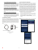
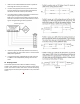
14 AVPTCMotorOrientaon
If the unit is in the upow posion, there is no need to rotate the
motor. If the unit is in the downow posion, loosen motor mount
and rotate motor as shown in the AVPTCMotorOrientaon gure
below. Be sure motor is oriented with the female connecons on
the casing down. If the motor is not oriented with the connecons
down, water could collect in the motor and may cause premature
failure.
FEMALE CONNECTIONS
SIDE VIEW
W
A
RNING
SOFTW
A
RE VER.
TOP
FRONT VIEW
AVPTC Motor Orientaon
Figure 13
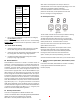
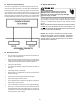
15CoolCloudHVACPhoneApplicaon
NOTE: This equipment has been tested and found to comply with
the limits for a Class B digital device, pursuant to part 15 of the FCC
Rules. These limits are designed to provide reasonable protecon
against harmful interference in a residenal installaon. This equip-
ment generates, uses and can radiate radio frequency energy and,
if not installed and used in accordance with the instrucons, may
cause harmful interference to radio communicaons. However,
there is no guarantee that interference will not occur in a parcular
installaon. If this equipment does cause harmful interference to
radio or television recepon, which can be determined by turning
the equipment o and on, the user is encouraged to try to correct
the interference by one or more of the following measures:
—Reorient or relocate the receiving antenna.
—Increase the separaon between the equipment and receiver.
—Connect the equipment into an outlet on a circuit dierent
from that to which the receiver is connected.
—Consult the dealer or an experienced radio/ TV technician
for help.
Actual screens may look dierent based on the mobile device
being used.
Figure 14