
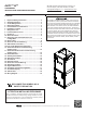
AVPTC ComfortBridge Air Handler Installation and Operation Manual

9
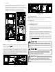
9 Ductwork
This air handler is designed for a complete supply and return
ductwork system.
To ensure correct system performance, the ductwork is to be
sized to accommodate 350-450 CFM per ton of cooling with the
static pressure not to exceed 0.5" in w.c. Refer to ACCA Manual
D, Manual S and Manual RS for information on duct sizing and
application. Flame retardant ductwork is to be used and sealed
to the unit in a manner that will prevent leakage.
NOTE: A downflow application with electric heat must have an L-
shaped sheet metal supply duct without any outlets or registers
located directly below the heater.
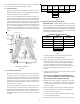
9.1 Return Ductwork
DO NOT LOCATE THE RETURN DUCTWORK IN AN AREA
THAT CAN INTRODUCE TOXIC, OR OBJECTIONABLE FUMES/
ODORS INTO THE DUCTWORK. The return ductwork is to
be connected to the air handler bottom (upflow configu-
ration).
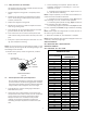
10 Return Air Filters
Each installation must include a return air filter. This filtering
may be performed at the air handler using the factory filter rails
or externally such as a return air filter grille. When using the
factory filter rails, a nominal 16x20x1”, 20x20x1” or 24x20x1”
(actual dimension must be less than 23-½”x20”) filter can be in-
stalled on a B, C and D cabinet respectively (the cabinet size is
the seventh letter of the model number).
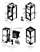
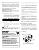
11 Achieving 1.4% and 2.0% Airflow Low Leakage Rate
Ensure all the gaskets remain intact on all surfaces as shipped
with the unit. These surfaces are areas between the upper tie
plate and coil access panel, blower access and coil access panels,
and between the coil access and filter access panels. Ensure upon
installation, that the plastic breaker cover is sitting flush on the
blower access panel and all access panels are flush with each
other and the cabinet. With these requirements satisfied, the
unit achieves less than 1.4% airflow leakage @ 0.5 inch wc static
pressure and less than 2% airflow leakage @1inch wc static pres-
sure when tested in accordance with ASHRAE Standard 193.
12 Electric Heat
Do not operate this product without all the ductwork
attached.
Refer to the installation manual provided with the electric heat
kit for the correct installation procedure. All electric heat must
be field installed. If installing this option, the ONLY heat kits that
are permitted to be used are the HKS series. Refer to the air han-
dler unit’s Serial and Rating plate or the HKS specification sheets
to determine the heat kits compatible with a given air handler.
No other accessory heat kit besides the HKS series may be in-
stalled in these air handlers.
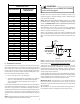
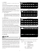
The heating mode temperature rise is dependent upon the sys-
tem airflow, the supply voltage, and the heat kit size (kW) selected.
Use data provided in Tables 3, 4 and 5 to determine the tempera-
ture rise (°F).
3 5 6 8 10 15 19/20 25
800 121923313756
1000 9 1519253044
1200 8 12152125374962
1400 7 11131821324253
1600 6 9 12 15 19 28 37 46
1800 5 8 10 14 16 25 33 41
2000 5 7 9 1215223037
CFM
HEAT KIT NOM INAL kW
230/1/60 SUPPLY VOLTAGE - TEMP. RISE °F
Table 2
3568101519/2025
800 111822303554
1000 9 1418242842
1200 7 12152024354759
1400 6 10131720304051
1600 6 9 11 15 18 27 35 44
1800 5 8 10 13 16 24 31 39
2000 4 7 9 12 14 21 28 35
CFM
HEAT KIT NOMINAL kW
220/1/60 SUPPLY VOLTAGE - TEMP. RISE °F
Table 3
3568101519/2025
800 1017212833
1000 8 1317222740
1200 7 11141922334556
1400 6 10121619293848
1600 5 8 10 14 17 25 33 42
1800 5 7 9 12 15 22 30 37
2000 4 7 8 11 13 20 27 33
CFM
HEAT KIT NOMINAL kW
208/1/60 SUPPLY VOLTAGE - TEMP. RISE °F
Table 4
35681015192025
AVPTC25B14 550 650 700 800 850 875
AVPTC29B14 550 650 700 800 875 875
AVPTC35B14 550 650 700 800 875 1050
AVPTC37B14 550 650 700 800 875 1050
AVPTC31C14 600 700 770 880 970 1090 1280
AVPTC33C14 600 700 750 850 920 950
AVPTC37C14 700 770 880 970 1090 1280
AVPTC39C14 700 770 880 970 1090 1280
AVPTC49C14 800 800 950 1090 1290 1345
AVPTC59C14 800 800 950 1090 1290 1345
AVPTC37D14 870 970 1060 1120 1220 1250
AVPTC49D14 950 1060 1150 1220 1520
AVPTC59D14 990 1110 1200 1240 1520 1520
AVPTC61D14 1030 1150 1250 1320 1650 1690 1750
HEATER (kW)
Model
MINIMUM CFM REQUIREMENTS FOR HEATER KITS
Table 5
NOTE: For installations not indicated above the following formula
is to be used:
TR = (kW x 3412) x (Voltage Correction) / (1.08 x CFM)
Where: TR = Temperature Rise
kW = Heater Kit Actual kW
3412 = Btu per kW
VC* = .96 (230 Supply Volts)
= .92 (220 Supply Volts)
= .87 (208 Supply Volts)
1.08 = Constant
CFM = Measured Airflow
VC* (Voltage Correction)