
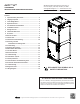
AVPTC 14 Series Installation and Operating Instructions

9
8 Condensate Drain Lines
The coil drain pan has a primary and a secondary drain with 3/4" NPT female connections. The connectors required are 3/4" NPT male,
either PVC or metal pipe, and should be hand tightened to a torque of no more than 37 in-lbs. to prevent damage to the drain pan
connection. An insertion depth of approximately 3/8” to 1/2” (3-5 turns) should be expected at this torque.
1. Ensure drain pan hole is not obstructed.
2. To prevent potential sweating and dripping on to finished space, it may be necessary to insulate the condensate drain line located
inside the building. Use Armaflex
®
or similar material.
A secondary condensate drain connection has been provided for ar-
eas where the building codes require it. Pitch all drain lines a mini-
mum of 1/4" per foot to provide free drainage. Provide required
support to the drain line to prevent bowing. If the secondary drain
line is required, run the line separately from the primary drain and
end it where condensate discharge can be easily seen.
NOTE: Water coming from secondary line means the coil primary
drain is plugged and needs immediate attention.
Insulate drain lines located inside the building or above a finished living space to
prevent sweating. Install a condensate trap to ensure proper drainage.
NOTE: When units are installed above ceilings, or in other locations where
damage from condensate overflow may occur, it is MANDATORY to install a field
fabricated auxiliary drain pan under the coil cabinet enclosure.
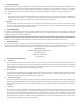
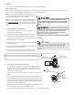
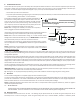
The installation must include a “P” style trap that is located as close as is practi-
cal to the evaporator coil. See Figure 12 for details of a typical condensate line
“P” trap.
NOTE: Trapped lines are required by many local codes. In the absence of any
prevailing local codes, please refer to the requirements listed in the Uniform
Mechanical Building Code.
A drain trap in a draw-through application prevents air from being drawn back through the drain line during fan operation thus
preventing condensate from draining, and if connected to a sewer line to prevent sewer gases from being drawn into the airstream
during blower operation.
Field experience has shown condensate drain traps with an open vertical Tee between the air handler and the condensate drain trap
can improve condensate drainage in some applications, but may cause excessive air discharge out of the open Tee. Goodman
®
does
not prohibit this type of drain but we also do not recommend it due to the resulting air leakage. Regardless of the condensate drain
design used, it is the installer’s responsibility to ensure the condensate drain system is of sufficient design to ensure proper conden-
sate removal from the coil drain pan.
Use of a condensate removal pump is permitted when necessary. This condensate pump should have provisions for shutting off the
control voltage should a blocked drain occur. A trap must be installed between the unit and the condensate pump.
IMPORTANT NOTE: The evaporator coil is fabricated with oils that may dissolve styrofoam and certain types of plastics. Therefore, a
removal pump or float switch must not contain any of these materials.
Tip: Priming the “P” trap may avoid improper draining at the initial installation and at the beginning of the cooling season.
9 Ductwork
This air handler is designed for a complete supply and return ductwork system.
To ensure correct system performance, the ductwork is to be sized to accommodate 350-450 CFM per ton of cooling with the static
pressure not to exceed 0.5" in w.c. Refer to ACCA Manual D, Manual S and Manual RS for information on duct sizing and application.
Flame retardant ductwork is to be used and sealed to the unit in a manner that will prevent leakage.
NOTE: A downflow application with electric heat must have an L-shaped sheet metal supply duct without any outlets or registers
located directly below the heater.
9.1 Return Ductwork
DO NOT LOCATE THE RETURN DUCTWORK IN AN AREA THAT CAN INTRODUCE TOXIC, OR OBJECTIONABLE FUMES/ODORS INTO
THE DUCTWORK. The return ductwork is to be connected to the air handler bottom (upflow configuration).
10 Return Air Filters
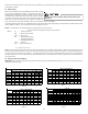
Each installation must include a return air filter. This filtering may be performed at the air handler using the factory filter rails or
externally such as a return air filter grille. When using the factory filter rails, a nominal 16x20x1”, 20x20x1” or 24x20x1” (actual
CAUTION
If secondary drain is not installed, the secondary
access must be plugged.
Air Handler
3" MIN.
POSITIVE LIQUID
SEAL REQUIRED
AT TRAP
Drain
Connection
2" MIN.
Figure 12