
AVPTC 14 Series Installation and Operating Instructions

8
NOTE: To adjust superheat, turn the valve stem clockwise to increase and counter clockwise to decrease.
b. If subcooling is low and superheat is high, add charge to raise subcooling to 5 to 7°F, and then check superheat.
c. If subcooling and superheat are high, adjust TXV valve to 7 to 9° superheat, then check subcooling.
d. If subcooling is high and superheat is low, adjust TXV valve to 7 to 9° superheat and remove charge to lower the subcooling to
5 to 7°F.
NOTE: Do NOT adjust the charge based on suction pressure unless there is a gross undercharge.
4. Disconnect manifold set, and installation is complete
NOTE: Check the Schrader ports for leaks and tighten valve cores if necessary. Install caps finger-tight.
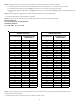
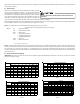
SUBCOOL FORMULA=
SAT. LIQUID LINE TEMP - LIQUID LINE TEMP
SUPERHEAT FORMULA=
SUCT. LINE TEMP - SAT. SUCT. TEMP
SUCTION PRESSURE LIQUID PRESSURE
PSIG R-22 R-410A PSIG R-22 R-410A
50 26 1 200 101 70
52 28 3 210 105 73
54 29 4 220 108 76
56 31 6 225 110 78
58 32 7 235 113 80
60 34 8 245 116 83
62 35 10 255 119 85
64 37 11 265 121 88
66 38 13 275 124 90
68 40 14 285 127 92
70 41 15 295 130 95
72 42 16 305 133 97
74 44 17 325 137 101
76 45 19 355 144 108
78 46 20 375 148 112
80 48 21 405 155 118
85 50 24 415 157 119
90 53 26 425 n/a 121
95 56 29 435 n/a 123
100 59 31 445 n/a 125
110 64 36 475 n/a 130
120 69 41 500 n/a 134
130 73 45 525 n/a 138
140 78 49 550 n/a 142
150 83 53 575 n/a 145
160 86 56 600 n/a 149
170 90 60 625 n/a 152
SATURATED SUCTION PRESSURE
TEMPERATURE CHART
SATURATED SUCTION
TEMPERATURE ºF
SATURATED LIQUID PRESSURE
TEMPERATURE CHART
SATURATED LIQUID
TEMPERATURE ºF
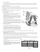
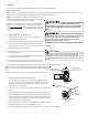
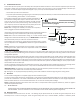
NOTE: The sensing bulb must be permanently located. A heat shield, heat trap, or wet rag must be used during brazing to
prevent damage to the TXV valve.
8. Replace access panels, suction line grommet, insulation and all screws.