
AVPTC 14 Series Installation and Operating Instructions

7
7.1 Tubing Size
For the correct tubing size, follow the specification for the condenser/heat pump.
7.2 Tubing Preparation
All cut ends are to be round, burr free, and clean. Failure to follow this practice increases the chances for refrigerant leaks. The
suction line is spun closed and requires tubing cutters to remove the closed end.
NOTE: To prevent possible damage to the tubing joints, do not
handle coil assembly with manifold or flowrator tubes. Always
use clean gloves when handling coil assemblies.
NOTE: The use of a heat shield is strongly recommended when
brazing to avoid burning the serial plate or the finish of the
unit.
Heat trap or wet rags must be used to protect heat sensi-
tive components such as service valves and TXV valves sensing
bulb.
7.3 Tubing Connections for TXV Models
TXV models come with factory installed TXV with the bulb
pre-installed on the vapor tube.
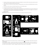
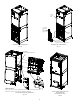
1. Remove refrigerant tubing panel or coil (lower) access panel.
2. Remove access valve fitting cap and depress the valve stem
in access fitting to release pressure. No pressure indicates possible leak.
3. Replace the refrigerant tubing panel.
4. Remove the spin closure on both the liquid and suction tubes
using a tubing cutter.
5. Insert liquid line set into liquid tube expansion and slide grom-
met about 18" away from braze joint.
6. Insert suction line set into suction tube expansion and slide
insulation and grommet about 18" away from braze joint.
7. Braze joints. Quench all brazed joints with water or a wet rag upon completion of brazing.
NOTE: The sensing bulb must be permanently located. A heat shield, heat
trap, or wet rag must be used during brazing to prevent damage to the TXV
valve.
8. Replace access panels, suction line grommet, insulation and all screws.
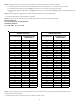
7.4 Thermal Expansion Valve System Adjustment
Run the system at Cooling for 10 minutes until refrigerant pressures
stabilize. Use the followung guidelines and methods to check unit
operation and ensure that the refrigerant charge is within limits.
Charge the unit on low stage.
1. Purge gauge lines. Connect service gauge manifold to base-valve service
ports.
2. Temporarily install a thermometer on the liquid line at the liquid line ser-
vice valve and 4-6’’ from the compressor on the suction line. Ensure the
thermometer makes adequate contact and is insulated for best possible
readings. Use liquid line temperatice to determine subcooling and vapor
temperature to determine superheat.
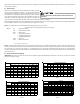
3. Check subcooling and superheat. Systems with TXV application should
have a subcooling of 5 to 7°F and superheat of 7 to 9°F
a. If subcooling and superheat are low, adjust TXV to 7 to 9°F, and then check subcooling.
This product is factory-shipped with R410A and dry
nitrogen mixture gas under pressure. Use appropriate
service tools and follow these instructions to prevent
injury.
A quenching cloth is strongly recommended to prevent
scorching or marring of the equipment finish when
brazing close to the painted surfaces. Use brazing
alloy of 5% minimum silver content.
Applying too much heat to any tube can melt the tube. Torch
heat required to braze tubes of various sizes must be
proportional to the size of the tube. Service personnel must
use the appropriate heat level for the size of the tube being
brazed.
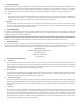
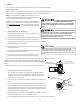
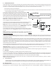
CAUTION
REFRIGERANT BULB
MUST BE POSITIONED
BETWEEN 10 & 2 O’CLOCK
REFRIGERANT BULB
MUST BE POSITIONED
BETWEEN 10 & 2 O’CLOCK
Figure 10
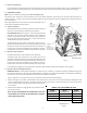
RUBBER
GROMMET
SUCTION LINE
WITH SPIN CLOSURE
Suction Line Grommet
Figure 11