
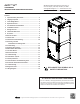
AVPTC 14 Series Installation and Operating Instructions

5
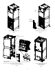
3. Removal of the center support is required on units with 21" wide cabinet. Remove and retain the two (2) screws that secure the
center support to the cabinet. Remove the center support.
4. Using the drain pan to hold the coil assembly, slide the coil assembly back into the cabinet on the downflow brackets as shown in
Figure 8.
5. Re-install the center support (if removed) using the two (2) screws removed in Step 4.
6. Re-install the access panels removed in Step 1 as shown in Figure 9.
7. The bottom left drain connection is the primary drain for this application and condensate drain line must be attached to this
drain connection. The top connection of the three drain connections on the drain pan must remain plugged for this application.
The bottom left drain connection is for the secondary drain line (if used).
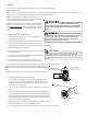
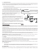
7 Refrigerant Lines
NOTE: Refrigerant tubing must be routed to allow adequate access for servicing and maintenance of the unit.
NOTE: If removing only the coil access panel from the unit, the filter access panel must be removed first. Failure to do so may result
in panel damage.
Do not install the air handler in a location that violates the instructions provided with the condenser. If the unit is located in an
unconditioned area with high ambient temperature and/or high humidity, the air handler may be subject to nuisance sweating of
the casing. On these installations, a wrap of 2" fiberglass insulation with a vapor barrier is recommended.
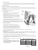
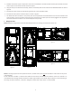
DOWNFLOW
Figure 3
UPFLOW
Figure 2
HORIZONTAL RIGHT
Figure 5
HORIZONTAL LEFT
Figure 4