
AVPTC 14 Series Installation and Operating Instructions

4
5.5 Horizontal Applications
If installed above a finished living space, a secondary drain pan (as required by many building codes), must be installed under the
entire unit and its condensate drain line must be routed to a location such that the user will see the condensate discharge.
6 Installation Location
NOTE: These air handlers are designed for indoor installation only.
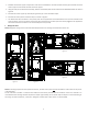
The AVPTC**14** product line may be installed in one of the upflow, downflow, horizontal left or horizontal right orientations as
shown in Figures 2, 3, 4 and 5. The unit may be installed in upflow or horizontal left orientation as shipped (refer to specific sections for
more information).
Minor field modifications are necessary to convert to downflow or hori-
zontal right as indicated in below sections.
6.1 Upflow Installation
No field modifications are mandatory however to obtain maximum
efficiency, the horizontal drip shield must be removed.
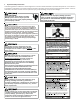
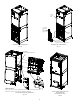
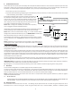
Drip Shield Removal: Refer to Figure 1, remove the two (2) screws
that secure the drip shield support brackets to the condensate
collectors (one screw per side). Remove the two (2) screws that
secure the drip shield to the drain pan. The drip shield and drip
shield brackets may now be removed.
The bottom left drain connection is the primary drain for this ap-
plication and condensate drain line must be attached to this drain
connection. The top connection of the three drain connections on
the drain pan must remain plugged for this application. The bot-
tom right drain connection is for the secondary drain line (if used).
6.2 Horizontal Left Installation
No field modifications are permissible for this application.
The bottom right drain connection is the primary drain for this
application and condensate drain line must be attached to this drain
connection. The top connection of the three drain connections on
the drain pan must remain plugged for this application. The bot-
tom left drain connection is for the secondary drain line (if used).
Use condensate management kit if equipment is installed in high humidity condition (for example: 70% or higher).
6.3 Downflow/Horizontal Right Installation
IMPORTANT NOTE: In the downflow application, to prevent coil pan “sweating”, a downflow kit (DFK) is available through your
local Goodman distributor. The DFK is not supplied with the air handler and is required by Goodman on all downflow installations.
See Table 2 for the correct DFK and follow the instructions provided for installation.
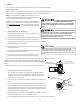
Refer to Figure 6 and 7 for the location of the components referenced in the following steps.
1. Before inverting the air handler, remove blower access panel and coil access panel. The coil access panel and tubing panel may
remain screwed together during this procedure. Remove and retain the seven (7) screws securing the coil access panel to the
cabinet and the six (6) screws securing the blower access panel
to the cabinet.
2. Slide the coil assembly out using the drain pan to pull the assem-
bly from the cabinet.
NOTE: DO NOT USE MANIFOLDS OR FLOWRATOR TO PULL THE
COIL ASSEMBLY OUT. FAILURE TO DO SO MAY RESULT IN BRAZE
JOINT DAMAGE AND LEAKS.
DRIP SHIELD REMOVAL
Figure 1
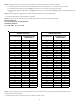
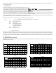
DOWNFLOW KIT
Table 1
DFK-B
Downflow Kit
DFK-C
Downflow Kit
DFK-D
Downflow Kit
AVPTC25B14** AVPTC31C14** AVPTC37D14**
AVPTC29B14** AVPTC37C14** AVPTC49D14**
AVPTC37B14** AVPTC59C14** AVPTC59D14**
AVPTC61D14**
MODEL LIST FOR DOWNFLOW KITS