
AVPTC 14 Series Installation and Operating Instructions

18
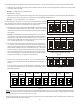
NOTE: Airflow blink codes are approximations of actual airflow. Airflows provided
are at 0.3 static.
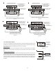
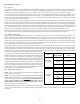
TAPS1S2S3S4S5S6S12S13
A OFFOFFOFFOFFOFFOFFOFF OFF
B ON OFF ON OFF ON OFF ON OFF
C OFF ON OFF ON OFF ON OFF ON
D ONONONONONONON ON
A
B
C
D
SPEED SELECTION DIP SWITCHES
COOL
SELECTION
SWITCHES
ADJUST
SELECTION
SWITCHES
PROFILE
SELECTION
SWITCHES
CONTINUOUS
FAN
SPEED
PROFILES PRE-RUN SHORT-RUN OFF DELAY
---- ---- 60 SEC. / 100%
---- 30 SEC. / 50% 60 SEC. / 100%
TO SET AIRFLOW
: (1) Select model and desired HIGH STAGE COOLING
AIRFLOW. Determine the corresponding TAP (A, B, C, D). Set DIP switches S1
and S2 to the appropriate ON / OFF positions.
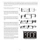
(2) Select model and installed electric heater size. Set DIP switches S9, S10
and S11 to the appropriate ON / OFF positions.
(3) If airflow a djustment is re quired, set TRIM ENABLE SWITCH S8 to ON (OFF =
0% Trim) and set S3 and S4 to appropriate ON / OFF positions. TAP A is +5%,
TAP B is -5%, TAP C is +10%. TAP D is -10%.
TO SET COMFORT MODE:
Select desired Comfort Mode Profile. (see
profiles above). Set DIP switches S5 and S6 to appropriate ON / OFF positions.
DEHUMIDIFICATION:
To enable, set DIP switch S7 to ON. Cooling airflow will
be reduced to 85% of nominal value during cool call when DEHUM command is
present. To disable, set S7 to OFF.
CONTINUOUS FAN SPEED
: Use DIP switches S12 and S13 to select one of
the 4 continuous fan speeds, TAP A is 25%, TAP B is 50%, TAP C is 75%, TAP
D is 100%.
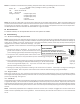
NOTES:
1. Airflow data shown applies to legacy mode operation only. For a fully
communicating system, please see the outdoor unit's installation instructions for
cooling and heat pump airflow data. See
ComfortNet System-Airflow
Consideration
section for details.
2. Airflow blink codes are approximations of actual airflow.
---- 7.5 MIN. / 82% 60 SEC. / 100%
30 SEC. / 50% 7.5 MIN. / 82% 30 SEC. / 50%
MODEL
Tap Low Stage High Stage
A 445 650
B 600 855
C 690 980
D 745 1085
A 375 610
B 545 795
C 630 930
D 740 1085
A 590 880
B 705 1055
C 845 1265
D 910 1360
A 610 875
B 810 1225
C 940 1410
D 1070 1595
A 605 900
B 725 1080
C 820 1225
D 940 1405
A 1040 1445
B 1260 1790
C 1330 1890
D 1395 1990
A 820 1195
B 895 1320
C 995 1460
D 1056 1530
A 1080 1630
B 1210 1820
C 1280 1925
D 1350 2025
AVPTC59D14
AVPTC49D14
AVPTC61D14
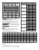
COOLING / HEAT PUMP AIRFLOW TABLE
AVPTC25B14
AVPTC29B14
AVPTC37B14
AVPTC31C14
AVPTC37C14
AVPTC59C14
AVPTC37D14
DIP SWITCH SETTING & AIRFLOW TABLE FOR ELECTRIC HEAT
HTR
KW
S9 S10 S11 AVPTC25B14 AVPTC29B14 AVPTC37B14
AVPTC31C14
AVPTC37C14
AVPTC59C14
AVPTC37D14
AVPTC59D14
AVPTC49D14 ƚƚ AVPTC61D14 ƚƚƚ
3 ON ON ON 550 550 550 NR NR NR NR NR
5 ON ON OFF 650 650 650 850 1170 1240 1250 1250
6 ON OFF ON 700 700 700 900 1170 1240 1300 1300
8 ON OFF OFF 800 800 800 1000 1170 1240 1500 1500
10 OFF ON ON 850 875 875 1170 1170 1240 1550 1550
15 OFF ON OFF 875 875 1050 1345 1345 1520 1720 1780
19* OFF OFF ON NR NR NR 1345 1345 NR NR NR
20 OFF OFF ON NR NR NR NR NR 1520 NR 1850
21
OR 25
OFFOFFOFFNRNRNRNRNRNR NR 1850
Note: Ai rfl ow data s hown appl i es to the el ectri c heat onl y i n ei ther legacy mode or communi ca ting mode operati on
* Within thermostat user menu CTK0* communicating thermostat will display 20KW for OFF- OFF- ON dip switch selection, 21kW for OFF-OFF-OFF dip switch
selection.
21kW for OFF-OFF-OFF dip switch selection.
NR - Not rated
†† For match up wi th a 3 ton outdoor uni t:
Airfl ow for 5 kW up to 15 kW heater ki ts s ha ll be set to 1300 cfm s peed tap of ON-OFF-ON.
††† For ma tch up wi th a 3.5 ton outdoor uni t: Heater ki t a ppl i caƟon s ha ll not exceed 20 kW.
Airfl ow for 5 kW up to 20 kW heater ki ts s ha ll be set to 1620 cfm s peed tap of ON-OFF-ON.