
AVPTC 14 Series Installation and Operating Instructions

17
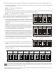
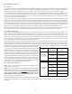
NOTE: For installations not indicated in the preceding Temperature Rise Tables, the following formula is to be used:
TR = (kW x 3412) x (Voltage Correction) / (1.08 x CFM)
Where: TR = Temperature Rise
kW = Heater Kit Actual kW
3412 = Btu per kW
Voltage Correction =.96 (230 Supply Volts)
=.92 (220 Supply Volts)
=.87 (208 Supply Volts)
1.08 = Constant
CFM = Measured Airflow
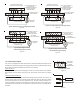
NOTE: The Temperature Rise Tables can also be used to determine the air handler airflow delivery. When using these tables for this
purpose set the room thermostat to maximum heat and allow the system to reach steady state conditions. Insert two thermometers,
one in the return air and one in the supply air. The temperature rise is the supply air temperature minus the room air temperature.
Use HKR specification sheets to determine the HKR available for a given air handler.
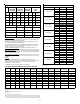
18 Heat Kit Selection
For heat kit selection, see the Specification Sheet for each specific Air Handler.
19 Troubleshooting
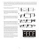
19.1 Electrostatic Discharge (ESD) Precautions
NOTE: Discharge body’s static electricity before touching unit. An electrostatic discharge can adversely affect electrical components.
Use the following precautions during air handler installation and servicing to protect the integrated control module from damage. By
putting the air handler, the control, and the person at the same electrostatic potential, these steps will help avoid exposing the
integrated control module to electrostatic discharge. This proce-
dure is applicable to both installed and uninstalled (ungrounded)
blowers.
1. Disconnect all power to the blower. Do not touch the inte-
grated control module or any wire connected to the control
prior to discharging your body’s electrostatic charge to ground.
2. Firmly touch a clean, unpainted, metal surface of the air han-
dler blower near the control. Any tools held in a person’s hand during grounding will be d i s -
charged.
3. Service integrated control module or connecting wiring following the discharge process in step 2.
Use caution not to recharge your body with static electricity; (i.e., do not move or shuffle your feet,
do not touch ungrounded objects, etc.). If you come in contact with an ungrounded object, re-
peat step 2 before touching control or wires.
4. Discharge your body to ground before removing a new control from its container. Follow steps 1 through 3 if installing the
control on a blower. Return any old or new controls to their containers before touching any ungrounded object.
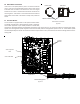
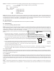
19.2 Diagnostic Chart
Refer to the Troubleshooting Chart at the end of this manual for assistance in determining the source of unit operational problems.
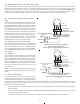
The 7 segment LED display will provide any active fault codes. An arrow printed next to the display indicates proper orientation (arrow
points to top of display). See Figure 31.
19.3 Fault Recall
The integrated control module is equipped with a momentary push-button switch that can be used to display the last six faults on the
7 segment LED display. The control must be in Standby Mode (no thermostat inputs) to use the feature. Depress the push-button for
approximately two seconds and less than five seconds. The LED display will then display the six most recent faults beginning with the
most recent fault and decrementing to the least recent fault. The faults may be cleared by depressing the button for greater than five
seconds.
NOTE: Consecutively repeated faults are displayed a maximum of three times. Example: A clogged return air filter causes the air
handler’s motor to repeatedly enter a limiting condition. The control will only store this fault the first three consecutive times the fault
occurs.
HIGH VOLTAGE!
T
O
AVOID
PERSONAL
INJURY
OR
DEATH
DUE
TO
ELECTRICAL
SHOCK
,
DISCONNECT
ELECTRICAL
POWER
BEFORE
PERFORMING
ANY
SERVICE
OR
MAINTENANCE
.
WARNING
7 Segment
Diagnostic
Display
Figure 31