
AVPTC 14 Series Installation and Operating Instructions

16
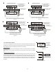
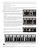
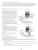
6. The multi-circulator blower also offers several custom ON/OFF ramping profiles. These profiles may be used to enhance cooling
performance and increase comfort level. The ramping profiles are selected using DIP switches 5 and 6. Refer to the following
Dip Switches - Cooling Airflow Ramping Profiles figure for switch positions and their corresponding taps. Refer to the bullet
points below for a description of each ramping profile. Verify profile selection by counting the green CFM LED blinks and timing
each step of the ramping profile.
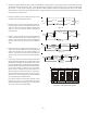
• Profile A provides only an OFF delay of one (1) minute
at 100% of the cooling demand airflow.
• Profile B ramps up to full cooling demand airflow by
first stepping up to 50% of the full demand for 30 sec-
onds. The motor then ramps to 100% of the required
airflow. A one (1) minute OFF delay at 100% of the
cooling airflow.
• Profile C ramps up to 82% of the full cooling demand
airflow and operates there for approximately 7 1/2
minutes. The motor then steps up to the full demand
airflow. Profile C also has a one (1) minute 100% OFF
delay.
• Profile D ramps up to 50% of the demand for 1/2
minute, then ramps to 82% of the full cooling demand
airflow and operates there for approximately 7 1/2
minutes. The motor then steps up to the full demand
airflow. Profile D has a 1/2 minute at 50% airflow OFF
delay.
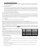
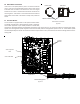
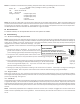
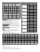
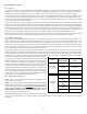
7. If an electric heater kit has been installed, determine
the heater kilowatt (kW) rating. Using the Electric Heat
Airflow table on page 16, set dip switches 9, 10, and 11
for the installed heater. The adjust setting (already es-
tablished by the cooling speed selection) also applies
to the electric heater kit airflow. Thus, the electric
heater airflow is adjusted by the same amount. This
does not apply to systems setup with a communicat-
ing thermostat. See Set-Up section in the AIR HANDLER
ADVANCED FEATURES MENU on page 22. Verify selected CFM
by counting the green CFM LED blinks.
If an electric heater kit has not been installed, set dip
switches 9, 10, and 11 to any valid heater kit setting
(see airflow table for valid settings). This will prevent
an Ec Error code from being displayed.
OFF
100% CFM 100% CFM
1 min
OFF
Figure 26
50% CFM
1/2 min
100% CFM
100% CFM
1 min
OFF
OFF
Figure 27
100% CFM
OFF
OFF
Figure 28
OFF
OFF
Figure 29
S5
S6
S5
S6
S5
S6
S5
S6
OFF OFF OFF OFFON ON ON ON
Tap A* Tap B Tap C Tap D
Dip Switches - Cooling Airflow Ramping Profiles
Figure 30